INSTRUCTION MANUAL MANUAL DE INSTRUCCIONES Cordless Compound Miter Saw Sierra de Inglete Inalámbrica XSL05 IMPORTANT: Read Before Using. IMPORTANTE: Lea antes de usar.
ENGLISH (Original instructions) SPECIFICATIONS Model: XSL05 Blade diameter 165 mm (6-1/2") Hole (arbor) diameter 15.88mm (5/8") Max. miter angle Left 52°, Right 52° Max. bevel angle Left 45° (46° when using release lever), Right 45° (46° when using release lever) No load speed (RPM) 5,000 /min Laser type Wavelength 655 nm, Maximum output Dimensions (L x W x H) 1mW (Laser Class II) 340 mm x 400 mm x 440 mm (13-3/8" x 15-3/4" x 17-1/4") Rated voltage D.C.
5. 6. 7. When operating a power tool outdoors, use an extension cord suitable for outdoor use. Use of a cord suitable for outdoor use reduces the risk of electric shock. If operating a power tool in a damp location is unavoidable, use a ground fault circuit interrupter (GFCI) protected supply. Use of a GFCI reduces the risk of electric shock. Power tools can produce electromagnetic fields (EMF) that are not harmful to the user.
6. 7. Do not expose a BATTERY pack or tool to fire or excessive temperature. Exposure to fire or temperature above 130 °C may cause explosion. Follow all charging instructions and do not charge the BATTERY pack or tool outside the temperature range specified in the instructions. Charging improperly or at temperatures outside the specified range may damage the BATTERY and increase the risk of fire. 5. 6. Service 1.
16. 17. 18. 19. 20. 21. 22. If the workpiece or blade becomes jammed, turn the mitre saw off. Wait for all moving parts to stop and disconnect the plug from the power source and/or remove the battery pack. Then work to free the jammed material. Continued sawing with a jammed workpiece could cause loss of control or damage to the mitre saw. After finishing the cut, release the switch, hold the saw head down and wait for the blade to stop before removing the cut-off piece.
10. Symbols The followings show the symbols used for tool. volts direct current no load speed revolutions or reciprocation per minute 11. SAVE THESE INSTRUCTIONS. Do not place hand or fingers close to the blade. CAUTION: Only use genuine Makita batteries. Use of non-genuine Makita batteries, or batteries that have been altered, may result in the battery bursting causing fires, personal injury and damage. It will also void the Makita warranty for the Makita tool and charger.
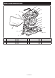
PARTS DESCRIPTION 1 2 3 15 4 14 5 6 7 8 8 13 12 9 10 11 1 Lock-off button 2 Switch trigger 3 Handle 4 Blade case 5 Blade 6 Blade guard 7 Sub-fence 8 Small sub-fence Vertical vice 9 Base 10 Turn base 11 Guide fence 12 13 Dust bag 14 Dust nozzle 15 Center cover - 7 ENGLISH -
16 24 23 17 22 21 18 20 19 16 Lamp 17 Battery cartridge 18 Hex wrench 19 Release lever 20 Lever (for bevel angle adjustment) 21 Kerf board 22 Lower limit adjusting bolt 23 Lamp switch 24 Laser switch - - - - - INSTALLATION Bench mounting WARNING: Ensure that the tool does not move on the supporting surface. Movement of the miter saw on the supporting surface while cutting may result in loss of control and serious personal injury. 1.
Tool / battery protection system FUNCTIONAL DESCRIPTION The tool is equipped with a tool/battery protection system. This system automatically cuts off power to the motor to extend tool and battery life. The tool will automatically stop during operation if the tool or battery is placed under one of the following conditions: WARNING: Always be sure that the tool is switched off and the battery cartridge is removed before adjusting or checking the functions on the tool.
When you pull the switch trigger, the battery indicator indicates the remaining battery capacity. Battery indicator status On Off NOTE: Depending on the conditions of use and the ambient temperature, the indication may differ slightly from the actual capacity. Remaining battery capacity Automatic speed change function Blinking 50% to 100% 20% to 50% 0% to 20% 1 Charge the battery Indicating the remaining battery capacity ► 1.
1. Make sure that the tool is switched off and the battery cartridges are removed. Blade guard 2. Turn the hex socket bolt counterclockwise using the supplied hex wrench with holding the center cover. WARNING: Never defeat or remove the blade guard or the spring which attaches to the guard. An exposed blade as a result of defeated guarding may result in serious personal injury during operation. 3. Raise the blade guard and center cover. 4.
1 1 2 3 2 3 4 5 1 ► 1. Guide fence ► 1. Saw blade 2. Blade teeth 3. Kerf board 4. Left bevel cut 5. Straight cut 5. Tighten the screws (do not tighten firmly). 6. After adjusting the kerf boards, release the stopper pin and raise the handle. Then tighten all the screws securely. NOTICE: After setting the bevel angle ensure that the kerf boards are adjusted properly. Correct adjustment of the kerf boards helps to provide proper support of the workpiece and minimizing workpiece tear out. 3.
1. Loosen the fixing screw counterclockwise. 2. Adjust the angle of the turn base. Use the pointer and the miter scale as a guide. 3. Tighten the fixing screw clockwise firmly. CAUTION: After changing the miter angle, always secure the turn base by tightening the fixing screw firmly. NOTICE: When turning the turn base, be sure to raise the handle fully. 1 Adjusting the bevel angle ► 1. Sub-fence To adjust the bevel angle, turn the lever at the rear of the tool downward.
1 1 2 ► 1. Release button ► 1. Lever 2. Release lever 3. Turn the lever upward firmly to secure the saw head. CAUTION: After changing the bevel angle, always secure the saw head by turning the lever upward firmly. Adjusting the lever position NOTICE: When tilting the saw blade, be sure the If the lever does not provide full tightening in course of time, change the position of the lever. The lever can be repositioned at every 30° angle. Loosen and remove the screw that secures the lever.
Switch action Lighting up the lamp WARNING: Before installing the battery cartridge on the tool, always check to see that the switch trigger actuates properly and returns to the "OFF" position when released. Operating a tool with a switch that does not actuate properly can lead to loss of control and serious personal injury. CAUTION: This is not a rainproof light. Do not wash the light in water or use it in a rain or a wet area. Such a conduct can cause an electric shock and fume.
1 B A ► 1. Laser switch NOTE: Be sure to turn off the switch as turning on the switch consumes the battery power. Laser line can be shifted to either the left or right side of the saw blade by turning the adjusting screw as follows. A) When you want to obtain the correct size on the left side of workpiece, shift the laser line to the left of the blade. B) When you want to obtain the correct size on the right side of workpiece, shift the laser line to the right of the blade.
Installing or removing saw blade WARNING: Always be sure that the tool is switched off and the battery cartridge is removed before installing or removing the blade. Accidental start up of the tool may result in serious personal injury. CAUTION: Use only the Makita hex wrench provided to install or remove the blade. Failure to do so may result in overtightening or insufficient tightening of the hex socket bolt. This could cause an injury. To remove the blade, perform the following steps: 2 1.
2 1 2 ► 1. Saw blade 2. Arrow 2. Install the outer flange and hex socket bolt, and then use the hex wrench to tighten the hex socket bolt (left-handed) of the spindle securely counterclockwise while pressing the shaft lock. Securing workpiece 3. Return the blade guard and center cover to its original position. Then tighten the hex socket bolt of the center cover clockwise to secure the center cover. 4. Release the handle from the raised position by pulling the stopper pin.
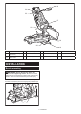
OPERATION 1 7 WARNING: Make sure the blade is not contacting the workpiece, etc. before the switch is turned on. Turning the tool on with the blade in contact with the workpiece may result in kickback and serious personal injury. 3 2 6 5 WARNING: After a cutting operation, do not raise the blade until it has come to a complete stop. The raising of a coasting blade may result in serious personal injury and damage to the workpiece. 3 4 ► 1. Vise arm 2. Vise knob 3. Guide fence 4. Turn base 5.
Bevel cut Compound cutting WARNING: After setting the blade for a bevel cut, before operating the tool ensure that the saw head and blade will have free travel throughout the entire range of the intended cut. Interruption of the saw head or blade travel during the cutting operation may result in kickback and serious personal injury. Compound cutting is the process in which a bevel angle is made at the same time in which a miter angle is being cut on a workpiece.
Align the cutting line on your workpiece with either the left or right side of the groove in the kerf board, and while holding the workpiece, move the set plate flush against the end of the workpiece. Then secure the set plate with the screw. When the set plate is not used, loosen the screw and turn the set plate out of the way. MAINTENANCE WARNING: Always be sure that the blade is sharp and clean for the best and safest performance.
1 1 2 3 2 ► 1. Guide fence 2. Hex socket bolt ► 1. Screw 2. Miter scale 3. Pointer Bevel angle 1 2 0° bevel angle 1. Lower the handle fully and lock it in the lowered position by pushing in the stopper pin. 2. Loosen the lever at the rear of the tool. 3. Turn the 0° bevel angle adjusting bolt on the right side of the saw head two or three revolutions counterclockwise to tilt the blade to the right. ► 1. Guide fence 2. Hex socket bolt 5.
5. Make sure that the pointer on the arm indicates 0° on the bevel scale. If it does not indicate 0°, loosen the screw which secures the pointer and adjust the pointer so that it indicates 0°. 1 Adjusting the laser line position WARNING: The battery cartridge must be installed on the tool while adjusting the laser line. Take extra care not to switch on the tool during adjustment. Accidental start up of the tool may result in serious personal injury. CAUTION: Never look directly into the laser beam.
Adjusting the laser line on the right side of the blade 2 1 1 ► 1. Vise 5. Install the battery cartridge to the tool and turn on the laser switch. 4 3 6. Loosen the adjusting screw. To move the laser line away from the blade, turn the range adjustment screws counterclockwise. To move the laser line close to the blade, turn the range adjustment screw clockwise. Adjusting the laser line on the left side of the blade 1 ► 1. Range adjustment screw 2. Hex wrench 3. Laser line 4. Saw blade 7.
MAKITA LIMITED ONE YEAR WARRANTY Warranty Policy Every Makita tool is thoroughly inspected and tested before leaving the factory. It is warranted to be free of defects from workmanship and materials for the period of ONE YEAR from the date of original purchase. Should any trouble develop during this one year period, return the COMPLETE tool, freight prepaid, to one of Makita’s Factory or Authorized Service Centers.
ESPAÑOL (Instrucciones originales) ESPECIFICACIONES Modelo: XSL05 Diámetro del disco 165 mm (6-1/2″) Diámetro del orificio (eje) 15,88 mm (5/8") Ángulo de inglete máximo Izquierda 52°, Derecha 52° Ángulo de bisel máximo Izquierdo a 45° (a46° al usar la palanca de liberación), Derecho a 45° (a46° al usar la palanca de liberación) Velocidad sin carga (r.p.m.
Seguridad eléctrica 1. Las clavijas de conexión de las herramientas eléctricas deberán encajar perfectamente en la toma de corriente. No modifique nunca la clavija de conexión de ninguna forma. No utilice ninguna clavija adaptadora con herramientas eléctricas que tengan conexión a tierra (puesta a tierra). La utilización de clavijas no modificadas y que encajen perfectamente en la toma de corriente reducirá el riesgo de que se produzca una descarga eléctrica. 2.
6. 7. 8. 9. Mantenga las herramientas de corte limpias y filosas. Si recibe un mantenimiento adecuado y tiene los bordes afilados, es probable que la herramienta se atasque menos y sea más fácil controlarla. Utilice la herramienta eléctrica, los accesorios y las brocas de acuerdo con estas instrucciones, considerando las condiciones laborales y el trabajo a realizar. Si utiliza la herramienta eléctrica para realizar operaciones distintas de las indicadas, podrá presentarse una situación peligrosa.
5. 6. 7. 8. 9. 10. 11. 12. No acerque las manos por detrás de la guía a más de 100 mm de distancia de ambos lados del disco de la sierra para extraer restos de madera ni por ninguna otra razón mientras el disco esté girando. La proximidad entre el disco de la sierra que está girando y su mano podría no ser obvia y ocasionarle una lesión grave. Inspeccione su pieza de trabajo antes de cortar.
4. 5. 6. 7. 8. 9. 10. 11. 12. 13. 14. 15. 16. 17. 18. No utilice la sierra sin los protectores puestos. Verifique que el protector del disco cierre debidamente antes de cada uso. No utilice la sierra si el protector del disco no se mueve libremente y se cierra instantáneamente. No sujete ni ate el protector del disco en la posición abierta. Mantenga las manos alejadas de la trayectoria del disco de la sierra. Evite el contacto con cualquier disco que esté girando por inercia.
Instrucciones importantes de seguridad para el cartucho de batería 1. 2. 3. 4. 5. 6. 7. 8. 9. 10. 11. Antes de utilizar el cartucho de batería, lea todas las instrucciones e indicaciones de precaución en el (1) el cargador de batería, (2) la batería, y (3) el producto con el que se utiliza la batería. No desarme el cartucho de batería. Si el tiempo de operación se ha acortado en exceso, deje de operar de inmediato.
DESCRIPCIÓN DE LAS PIEZAS 1 2 3 15 4 14 5 6 7 8 8 13 12 9 10 11 1 Botón de desbloqueo 2 Gatillo interruptor 3 Empuñadura 4 Caja del disco 5 Disco 6 Protector del disco 7 Guía auxiliar 8 Guía auxiliar pequeña 12 Prensa vertical 9 Base 10 Base giratoria 11 Guía lateral 13 Bolsa recolectora de polvo 14 Boquilla para polvo 15 Cubierta central 32 ESPAÑOL - -
16 24 23 17 22 21 18 20 19 16 Lámpara 17 Cartucho de batería 18 Llave hexagonal 19 Palanca de liberación 20 Palanca (para ajustar el ángulo de bisel) 21 Panel de corte 22 Perno de ajuste del límite inferior 23 Interruptor de la lámpara 24 Interruptor para el láser - - - - - - INSTALACIÓN Montaje en un banco de trabajo ADVERTENCIA: Asegúrese de que la herramienta no se mueva sobre la superficie de apoyo.
Sistema de protección para la herramienta/batería DESCRIPCIÓN DEL FUNCIONAMIENTO La herramienta está equipada con un sistema de protección de la herramienta/batería. Este sistema corta en forma automática el suministro de energía al motor para prolongar la vida útil de la herramienta y la batería.
Indicación de capacidad restante de la batería Oprima el botón de verificación en el cartucho de la batería para que indique la capacidad restante de la batería. Las luces indicadoras se iluminarán por algunos segundos. Luces indicadoras 1 Iluminadas Apagadas Capacidad restante Parpadeando 75% a 100% 50% a 75% 25% a 50% 0% a 25% ► 1. Indicador de batería Cargar la batería. Cuando jale el gatillo interruptor, el indicador de batería mostrará la capacidad restante de la batería.
Clavija de retención PRECAUCIÓN: Siempre sostenga la empuñadura al liberar la clavija de retención. De lo contrario, la empuñadura se levanta de golpe y puede provocar una lesión. Al bajar la empuñadura, el protector del disco se levanta automáticamente. El protector del disco es accionado por resorte, por lo que éste regresará a su posición original al terminar de realizar el corte y la empuñadura sea levantada.
AVISO: Tras ajustar el ángulo de bisel, asegure que los paneles de corte queden ajustados correctamente. El ajuste correcto de los paneles de corte ayudará a ofrecer un apoyo adecuado de la pieza de trabajo minimizando su desplazamiento. Manteniendo la máxima capacidad de corte 2 1 2 ► 1. Panel de corte 2. Tornillo 2. Vuelva a apretarlos sólo hasta el punto en que los paneles de corte puedan aún moverse manualmente con facilidad. 3.
1 ADVERTENCIA: Tras la colocación de un disco nuevo y con el cartucho de la batería retirado, asegúrese siempre de que el disco no haga contacto con ninguna pieza de la base inferior al bajar la empuñadura por completo. Si un disco hace contacto con la base, puede producirse un retroceso brusco ocasionando lesiones personales graves. 2 ► 1. Guía auxiliar pequeña 2. Escala Esta herramienta está equipada con guías auxiliares pequeñas.
Ajuste del ángulo de bisel PRECAUCIÓN: Después de cambiar el ángulo de bisel, asegure siempre la cabeza de la sierra girando la palanca firmemente hacia arriba. Para ajustar el ángulo de bisel, gire hacia abajo la palanca en la parte trasera de la herramienta. AVISO: Cuando incline el disco de la sierra, asegúrese de que la empuñadura esté levantada completamente.
El botón de desbloqueo es suministrado para evitar jalar accidentalmente el gatillo interruptor. Para encender la herramienta, presione el botón de desbloqueo y jale el gatillo interruptor. Para detenerla, suelte el gatillo interruptor. Ajuste de la posición de la palanca Si la palanca no se puede ajustar completamente con el transcurso del tiempo, cambie la posición de la palanca. La palanca puede reposicionarse en cada ángulo de 30°. Afloje y retire el tornillo que asegura la palanca.
1 1 2 ► 1. Tornillo de ajuste ► 1. Lámpara 2. Interruptor de la lámpara 1. Afloje el tornillo de ajuste girándolo en sentido inverso al de las manecillas del reloj. NOTA: Utilice un paño seco para quitar la suciedad de la lente de la lámpara. Tenga cuidado de no rayar la lente de la lámpara ya que la iluminación podría disminuir. 2. Con el tornillo de ajuste aflojado, deslice el tornillo de ajuste a la derecha o la izquierda tan lejos como llegue.
Freno eléctrico La herramienta está equipada con un freno eléctrico para el disco. Si la herramienta falla constantemente en detener el disco tras soltar el gatillo interruptor, lleve la herramienta a mantenimiento a un centro de servicio Makita. PRECAUCIÓN: Use solamente la llave hexagonal Makita proporcionada para instalar o retirar el disco. El no hacerlo puede ocasionar que el perno de cabeza hexagonal se apriete en exceso o no lo suficiente. Lo anterior podría provocar una lesión.
2 1 2 ► 1. Disco de la sierra 2. Flecha 2 1 3 2. Instale la brida exterior y el perno de cabeza hexagonal, y luego use la llave hexagonal para apretar el perno de cabeza hexagonal (a mano izquierda) del eje fijamente en sentido inverso al de las manecillas del reloj mientras presiona el eje de bloqueo. 3. Regrese el protector del disco y la cubierta central a su posición original.
Prensa vertical ADVERTENCIA: Asegure la pieza de trabajo firmemente contra la base giratoria y la guía lateral con la prensa durante todas las operaciones. De lo contrario, la pieza podría moverse durante la operación de corte causando daños al disco, y ser lanzada provocando la pérdida de control y lesiones personales graves. Instale la prensa vertical ya sea del lado izquierdo o derecho de la guía lateral.
Las piezas de trabajo de hasta 46 mm (1-13/16") de alto y 92 mm (3-5/8") de ancho pueden ser cortadas de la siguiente manera. 2 1 1. 2 2. Encienda la herramienta sin que el disco haga contacto alguno y espere a que éste adquiera velocidad completa antes de bajar la empuñadura. Asegure la pieza de trabajo con la prensa. 3. Luego baje lentamente la empuñadura a la posición completamente hacia abajo para realizar el corte en la pieza de trabajo. 4.
1. Afloje la palanca e incline el disco de la sierra para ajustar el ángulo de bisel (consulte la sección “Ajuste del ángulo de bisel” descrita anteriormente). Asegúrese de volver a ajustar con firmeza la palanca para fijar bien el ángulo de bisel seleccionado. 2. Asegure la pieza de trabajo con una prensa. 3. Encienda la herramienta sin que el disco haga contacto alguno y espere hasta que ésta alcance la velocidad máxima.
1. Retire el cartucho de batería. Ajuste del ángulo de corte 2. Fije el disco a un ángulo de bisel de 0° y la base giratoria por completo hasta la posición angular derecha de inglete. Esta herramienta ya viene cuidadosamente ajustada y alineada de fábrica, pero una manipulación descuidada podría afectar la alineación. Si su herramienta no está adecuadamente alineada, haga lo siguiente: Ángulo de inglete 1. Afloje el tornillo de fijación en sentido inverso al de las manecillas del reloj. 2.
Ángulo de bisel 1 2 Ángulo de bisel de 0° 1. Baje completamente la empuñadura y trábela en la posición inferior empujando la clavija de retención. 2. Suelte la palanca que se encuentra en la parte trasera de la herramienta. 3. Gire el perno de ajuste del ángulo de bisel de 0° del lado derecho de la cabeza de la sierra dos o tres revoluciones en sentido inverso al de las manecillas del reloj para inclinar el disco hacia la derecha. ► 1. Guía lateral 2. Perno de cabeza hexagonal 5.
Ajuste de la posición de la línea de láser 1 ADVERTENCIA: El cartucho de batería debe instalarse en la herramienta mientras se ajusta la línea de láser. Tenga sumo cuidado de no encender la herramienta durante el ajuste. El arranque accidental de la herramienta puede ocasionar lesiones personales graves. 2 PRECAUCIÓN: Nunca dirija la mirada directamente al rayo láser. La exposición directa de los ojos al rayo podría causar daños serios a su vista. 3 ► 1. Tornillo 2. Marcador 3.
Ajuste de la línea de láser del lado derecho del disco 2 1 1 ► 1. Prensa 5. Instale el cartucho de batería en la herramienta y active el interruptor para el láser. 4 3 6. Afloje el tornillo de ajuste. Para dirigir la línea de láser lejos del disco, gire los tornillos de ajuste de rango en sentido inverso al de las manecillas del reloj. Para dirigir la línea de láser cerca del disco, gire el tornillo de ajuste de rango en el sentido de las manecillas del reloj.
GARANTÍA LIMITADA DE UN AÑO DE MAKITA Ésta Garantía no aplica para México Política de garantía 1 ► 1. Lente AVISO: No retire el tornillo que fija el lente. Si el lente no sale, afloje el tornillo todavía más. AVISO: No utilice disolventes ni limpiadores a base de petróleo en el lente. Luego del uso Luego de utilizar la herramienta, limpie los restos de astillas y polvo con un paño o similar.
< USA only > WARNING Some dust created by power sanding, sawing, grinding, drilling, and other construction activities contains chemicals known to the State of California to cause cancer, birth defects or other reproductive harm. Some examples of these chemicals are: • lead from lead-based paints, • crystalline silica from bricks and cement and other masonry products, and • arsenic and chromium from chemically-treated lumber.