INSTRUCTION MANUAL MANUAL DE INSTRUCCIONES Cordless Trimmer Recortadora Inalámbrica XTR01 Read before use. Lea antes de usar. IMPORTANT: Read Before Using. IMPORTANTE: Lea antes de usar.
ENGLISH (Original instructions) SPECIFICATIONS Model: XTR01 Collet chuck capacity 1/4" or 3/8" No load speed 10,000 - 30,000/min Overall length 226 mm (8-7/8") Rated voltage D.C. 18 V Standard battery cartridge BL1815N / BL1820B / BL1830 / BL1830B / BL1840B / BL1850B / BL1860B Net weight • • • 1.8 - 2.1 kg (3.9 - 4.6 lbs) Due to our continuing program of research and development, the specifications herein are subject to change without notice.
5. 6. 7. 8. Do not overreach. Keep proper footing and balance at all times. This enables better control of the power tool in unexpected situations. Dress properly. Do not wear loose clothing or jewellery. Keep your hair and clothing away from moving parts. Loose clothes, jewellery or long hair can be caught in moving parts. If devices are provided for the connection of dust extraction and collection facilities, ensure these are connected and properly used.
10. 11. 12. 13. 14. 15. 16. 17. 18. Before using the tool on an actual workpiece, let it run for a while. Watch for vibration or wobbling that could indicate improperly installed bit. Be careful of the trimmer bit rotating direction and the feed direction. Do not leave the tool running. Operate the tool only when hand-held. Always switch off and wait for the trimmer bit to come to a complete stop before removing the tool from workpiece.
Indicating the remaining battery capacity FUNCTIONAL DESCRIPTION Only for battery cartridges with the indicator CAUTION: Always be sure that the tool is switched off and the battery cartridge is removed before adjusting or checking function on the tool. 1 Installing or removing battery cartridge CAUTION: Always switch off the tool before installing or removing of the battery cartridge. 2 CAUTION: Hold the tool and the battery cartridge firmly when installing or removing battery cartridge.
Overheat protection When the tool or battery is overheated, the tool stops automatically and the lamp blinks. In this case, let the tool and battery cool before turning the tool on again. Overdischarge protection When the battery capacity is not enough, the tool stops automatically. In this case, remove the battery from the tool and charge the battery. 1 Switch action To turn on the tool, press the lock/unlock button. The tool turns into the standby mode.
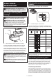
4. Push down the tool until the tip of the trimmer bit touches the flat surface, and then turn the fixing lever to secure the tool. NOTICE: If the tool is not secured after closing the lock lever, tighten the hex nut, and then close the lock lever. 2 1 1 ► 1. Fixing lever 2. Trimmer bit ► 1. Hex nut 5. Press down the stopper pole while pressing the feed button until it contacts the stopper screw. Adjusting cutting depth with the plunge base 1 Optional accessory 1.
1 1 2 ► 1. Stopper pole 2. Feed button ► 1. Fixing nut 8. To perform fine adjustment of the cutting depth, turn the dial on the stopper pole so that it indicates "0". 11. Release the fixing lever. 1 1 ► 1. Fixing lever ► 1. Dial 9. Turn the head of the stopper pole to obtain the desired depth. To increase the depth, turn the head counterclockwise. To decrease the depth, turn the head clockwise.
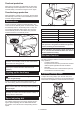
1 2 3 4 5 1 ► 1. Shaft lock 2. Loosen 3. Tighten 4. Wrench 5. Collet nut 1 2 3 ► 1. Lock lever 2. 1 Close the lock lever. 3. Attach the dust nozzle to the trimmer base, and then tighten the thumb screw. 4 ► 1. Wrench 2. Loosen 3. Tighten 4. Collet nut NOTE: The shaft lock may not return to the original position when you tighten the collet nut at the installation of the trimmer bit. The shaft lock returns to the original position when you start the tool. 1 1 2 ► 1. Dust nozzle 2.
Installing or removing the offset base 1 Optional accessory 1. Press the shaft lock, then loosen the collet nut. 1 2 3 ► 1. Base plate 5. Open the lock lever of the offset base, then insert the tool into the offset base. ► 1. Collet nut 2. Shaft lock 3. Wrench 2. 1 Remove the collet nut and the collet cone. 1 2 ► 1. Lock lever 6. Mount the belt to the pulley by rotating the belt manually. 1 ► 1. Collet nut 2. Collet cone 2 3.
1 2 1 3 ► 1. Lock lever ► 1. Collet nut 2. Wrench 3. Hex wrench 8. To remove the base, follow the installation procedure in reverse. Attach the base plate by tightening the screws. NOTE: You can also mount the belt to the pulley without removing the base plate as shown in the figure. 1 1 2 ► 1. Base plate 9. Insert the collet cone and the trimmer bit into the offset base, and then tighten the collet nut. ► 1. Pulley 2.
2. Close the lock lever. To remove the base, follow the installation procedure in reverse. Installing or removing the parallel ruler on the plunge base Optional accessory Insert the guide bars into the holes in the plunge base, and then tighten the wing bolts. To remove the ruler, follow the installation procedure in reverse. OPERATION 1 2 Using the tool with the trimmer base Set the tool base on the workpiece without the trimmer bit making any contact.
3. Loosen the wing nut on the straight guide and adjust the distance between the bit and the straight guide. At the desired distance, tighten the wing nut. 1 2 1 3 ► 1. Trimmer bit 2. Workpiece 3. Straight guide NOTICE: Since excessive cutting may cause overload of the motor or difficulty in controlling the tool, the depth of cut should not be more than 3 mm (1/8") at a pass when cutting grooves.
Using the straight guide for circular work For circular work, assemble the straight guide as shown in the figures. The minimum and maximum radius of circles to be cut (distance between the center of circle and the center of bit) are as follows: • Minimum: 70 mm (2-3/4") • Maximum: 221 mm (8-11/16") 1 2 For cutting circles between 70 mm (2-3/4") and 121 mm (4-3/4") in radius. ► 1. Nail 2.
1 NOTE: The actual cut size on the workpiece is slightly different from the templet. The difference is the distance (X) between the trimmer bit and the outside of the templet guide. The distance (X) can be calculated by using the following equation: Distance (X) = (outside diameter of templet guide trimmer bit diameter) / 2 ► 1. Clamp screw 2. Loosen the clamp screw and adjust the distance between the trimmer bit and the trimmer guide by turning the adjusting screw (1 mm (3/64") per turn).
Using the tool with the offset base The offset base is convenient for work in a tight area such as a corner. 1 2 ► 1. Bar type grip 2. Grip attachment Using the trimmer base with the offset base plate and grip The knob type grip removed from the plunge base can be installed on the offset base instead of the bar type grip. The offset base plate can also be used with a trimmer base and a grip attachment (optional accessory) for more stability. 1 1.
1 2 1 2 3 4 ► 1. Wing bolt 2. Guide holder 3. Wing nut 4. Straight guide 2. Loosen the wing nut on the straight guide and adjust the distance between the bit and the straight guide. At the desired distance, tighten the wing nut. ► 1. Screw 2. Templet guide 2. Operate the tool in the same way as the templet guide for the trimmer base. 1 Using the parallel ruler ► 1. Wing nut The parallel ruler is effectively used for straight cuts when chamfering or grooving.
MAINTENANCE A CAUTION: Always be sure that the tool is switched off and the battery cartridge is removed before attempting to perform inspection or maintenance. NOTICE: Never use gasoline, benzine, thinner, alcohol or the like. Discoloration, deformation or cracks may result. To maintain product SAFETY and RELIABILITY, repairs, any other maintenance or adjustment should be performed by Makita Authorized or Factory Service Centers, always using Makita replacement parts.
MAKITA LIMITED ONE YEAR WARRANTY Warranty Policy Every Makita tool is thoroughly inspected and tested before leaving the factory. It is warranted to be free of defects from workmanship and materials for the period of ONE YEAR from the date of original purchase. Should any trouble develop during this one year period, return the COMPLETE tool, freight prepaid, to one of Makita’s Factory or Authorized Service Centers.
ESPAÑOL (Instrucciones originales) ESPECIFICACIONES Modelo: XTR01 Capacidad de la pinza de sujeción 1/4″ o 3/8″ Velocidad sin carga 10 000 r/min - 30 000 r/min Longitud total 226 mm (8-7/8″) Tensión nominal 18 V c.c. Batería estándar BL1815N / BL1820B / BL1830 / BL1830B / BL1840B / BL1850B / BL1860B Peso neto • • • 1,8 kg - 2,1 kg (3,9 lbs - 4,6 lbs) Debido a nuestro continuo programa de investigación y desarrollo, las especificaciones aquí incluidas están sujetas a cambio sin previo aviso.
Seguridad personal 1. Manténgase alerta, preste atención a lo que está haciendo y utilice su sentido común cuando opere una herramienta eléctrica. No utilice una herramienta eléctrica cuando esté cansado o bajo la influencia de drogas, alcohol o medicamentos. Un momento de distracción mientras opera las herramientas eléctricas puede terminar en una lesión grave. 2. Use equipo de protección personal. Póngase siempre protección para los ojos.
4. 5. 6. 7. En condiciones abusivas, podrá escapar líquido de la batería; evite tocarlo. Si lo toca accidentalmente, enjuague con agua. Si hay contacto del líquido con los ojos, busque asistencia médica. Puede que el líquido expulsado de la batería cause irritación o quemaduras. No utilice una herramienta ni una batería que estén dañadas o hayan sido modificadas. Las baterías dañadas o modificadas podrían ocasionar una situación inesperada provocando un incendio, explosión o riesgo de lesiones.
Instrucciones importantes de seguridad para el cartucho de batería 1. 2. 3. 4. 5. 6. 7. 8. 9. 10. 11. Antes de utilizar el cartucho de batería, lea todas las instrucciones e indicaciones de precaución en el (1) el cargador de batería, (2) la batería, y (3) el producto con el que se utiliza la batería. No desarme el cartucho de batería. Si el tiempo de operación se ha acortado en exceso, deje de operar de inmediato.
Indicación de la capacidad restante de la batería DESCRIPCIÓN DEL FUNCIONAMIENTO PRECAUCIÓN: Asegúrese siempre de que la herramienta esté apagada y el cartucho de batería haya sido extraído antes de realizar cualquier ajuste o comprobación en la herramienta. Únicamente para cartuchos de batería con el indicador 1 Instalación o extracción del cartucho de batería PRECAUCIÓN: Apague siempre la herramienta antes de colocar o quitar el cartucho de batería.
Protección contra sobrecarga Iluminación de la luz delantera Cuando la batería se esté utilizando de una manera que cause que consuma una cantidad de corriente anormalmente alta, la herramienta se detendrá automáticamente sin indicación alguna. En este caso, apague la herramienta y detenga la aplicación que causó que la herramienta se sobrecargara. Luego encienda la herramienta para reiniciarla. PRECAUCIÓN: No mire a la luz ni vea a la fuente de luz directamente.
Funcionamiento electrónico La herramienta está equipada con funciones electrónicas para facilitar la operación. • Control de velocidad constante La función de control de velocidad permite una rotación constante independientemente de las condiciones de carga. • Arranque suave La función de arranque suave minimiza el impacto de encendido y hace que la herramienta se ponga en marcha suavemente. Ajuste de la profundidad de corte con la base de inmersión Accesorio opcional 1.
5. Presione hacia abajo la barra de tope mientras oprime el botón de alimentación hasta que éste haga contacto con el tornillo de tope. 1 1 ► 1. Selector 2 3 9. Gire la cabeza de la barra de tope para lograr la profundidad deseada. Para aumentar la profundidad, gire la cabeza en sentido inverso al de las manecillas del reloj. Para reducir la profundidad, gire la cabeza en el sentido de las manecillas del reloj. ► 1. Barra de tope 2. Tornillo de tope 3. Botón de alimentación 6.
1 2 3 1 4 1 ► 1. Palanca de fijación ► 1. Llave 2. Aflojar 3. Apretar 4. Tuerca de sujeción NOTA: El bloqueo del eje podría no regresar a la posición original cuando apriete la tuerca de sujeción durante la instalación de la fresa de la recortadora. El bloqueo del eje regresará a la posición original una vez que ponga en marcha la herramienta.
Instalación o extracción de la base descentrada Accesorio opcional 1. Presione el bloqueo del eje y luego afloje la tuerca de sujeción. 1 1 2 3 ► 1. Palanca de bloqueo 2. ► 1. Tuerca de sujeción 2. Bloqueo de eje 3. Llave Cierre la palanca de bloqueo. 2. 3. Coloque la boquilla para polvo en la base de la recortadora y luego apriete el tornillo de pulgar. Retire la tuerca de sujeción y el cono de sujeción. 1 2 ► 1. Tuerca de sujeción 2. Cono de sujeción 1 3.
1 1 ► 1. Placa de base ► 1. Palanca de bloqueo 5. Abra la palanca de bloqueo de la base descentrada y luego inserte la herramienta en la base descentrada. 8. Fije la placa de base apretando los tornillos. 1 1 ► 1. Placa de base 9. Inserte el cono de sujeción y la fresa de la recortadora en la base descentrada, y luego apriete la tuerca de sujeción. ► 1. Palanca de bloqueo 6. Instale la correa en la polea girando la correa manualmente. 1 1 2 2 3 ► 1. Fresa de la recortadora 2.
1 2 1 3 ► 1. Tuerca de sujeción 2. Llave 3. Llave hexagonal Para extraer la base, siga el procedimiento de instalación en orden inverso. NOTA: Usted también puede instalar la correa en la polea sin extraer la placa de base tal como se muestra en la ilustración. ► 1. Palanca de bloqueo 2. 1 Cierre la palanca de bloqueo. Para extraer la base, siga el procedimiento de instalación en orden inverso.
NOTA: Antes de cortar en la pieza de trabajo real, se recomienda hacer un corte de prueba. La velocidad de avance apropiada dependerá del tamaño de la fresa, el tipo de pieza de trabajo y la profundidad de corte. Si mueve la herramienta hacia delante muy de prisa podría ocasionar un corte de mala calidad, o dañar la fresa o el motor. Si mueve la herramienta hacia delante muy despacio podría quemar y arruinar el corte.
A 1 ► 1. Tornillo de fijación Uso de la guía recta para hacer un corte circular 3. Afloje la tuerca de mariposa en la guía recta y ajuste la distancia entre la fresa y la guía recta. En la distancia deseada, apriete la tuerca de mariposa. Para hacer un corte circular, ensamble la guía recta tal como se muestra en las ilustraciones.
Alinee el orificio central en la guía recta con el centro del círculo a ser cortado. Inserte un clavo de menos de 6 mm (1/4″) de diámetro en el orificio central para fijar la guía recta. Gire la herramienta alrededor del clavo en el sentido de las manecillas del reloj. 1 2 NOTA: El tamaño real del corte en la pieza de trabajo difiere ligeramente de la plantilla. La diferencia consiste en la distancia (X) entre la fresa de la recortadora y el exterior de la guía de plantilla.
Uso de la herramienta con la base descentrada 1 La base descentrada es conveniente para trabajar en un área reducida tal como una esquina. ► 1. Tornillo de fijación 2. Afloje el tornillo de fijación y ajuste la distancia entre la fresa de la recortadora y la guía de recorte girando el tornillo de ajuste (1 mm (3/64″) por vuelta). En la distancia deseada, apriete el tornillo de fijación para fijar la guía de recorte.
2. Fije la placa de base descentrada en la base de la recortadora apretando los tornillos. 1 3. Coloque el accesorio de la empuñadura y la empuñadura tipo barra en la placa de base descentrada apretando los tornillos. 2 3 4 1 ► 1. Perno de mariposa 2. Sujetador de la guía 3. Tuerca de mariposa 4. Guía recta 2 2. Afloje la tuerca de mariposa en la guía recta y ajuste la distancia entre la fresa y la guía recta. En la distancia deseada, apriete la tuerca de mariposa. ► 1.
A 1 2 ► 1. Tornillo 2. Guía de plantilla Cambio de la empuñadura tipo perilla a la empuñadura tipo barra 2. Opere la herramienta de la misma manera que la guía de plantilla para la base de la recortadora. Para instalar la empuñadura tipo barra en la base de inmersión, afloje el tornillo de la empuñadura tipo perilla, luego retire la empuñadura tipo perilla y después instale la empuñadura tipo barra apretándola.
GARANTÍA LIMITADA DE UN AÑO DE MAKITA MANTENIMIENTO PRECAUCIÓN: Asegúrese siempre de que la herramienta esté apagada y el cartucho de batería extraído antes de intentar realizar una inspección o mantenimiento. AVISO: Nunca use gasolina, bencina, diluyente (tíner), alcohol o sustancias similares. Puede que esto ocasione grietas o descoloramiento.
< USA only > WARNING Some dust created by power sanding, sawing, grinding, drilling, and other construction activities contains chemicals known to the State of California to cause cancer, birth defects or other reproductive harm. Some examples of these chemicals are: • lead from lead-based paints, • crystalline silica from bricks and cement and other masonry products, and • arsenic and chromium from chemically-treated lumber.
INSTRUCTION MANUAL MANUAL DE INSTRUCCIONES Cordless Slide Compound Miter Saw Sierra de Inglete Inalámbrica XSL03 XSL04 XSL06 IMPORTANT: Read Before Using. IMPORTANTE: Lea antes de usar.
ENGLISH (Original instructions) SPECIFICATIONS Model: XSL03 XSL04 Blade diameter 255 mm (10″) Hole diameter 15.88 mm (5/8″) Max. kerf thickness of the saw blade XSL06 3.2 mm (1/8″) Max. miter angle Right 60°, Left 60° Max. bevel angle Right 48°, Left 48° No load speed (RPM) 4,400 /min Laser type - Wavelength 655 nm, Maximum output 1mW (Laser Class II) Rated voltage D.C.
Personal Safety 1. Stay alert, watch what you are doing and use common sense when operating a power tool. Do not use a power tool while you are tired or under the influence of drugs, alcohol or medication. A moment of inattention while operating power tools may result in serious personal injury. 2. Use personal protective equipment. Always wear eye protection.
5. 6. 7. 8. 9. Service 1. Have your power tool serviced by a qualified repair person using only identical replacement parts. This will ensure that the safety of the power tool is maintained. 2. Never service damaged BATTERY packs. Service of BATTERY packs should only be performed by the manufacturer or authorized service providers. 3. Follow instruction for lubricating and changing accessories. Maintain power tools and accessories.
6. 7. 8. 9. 10. 11. 12. 13. 14. 15. 16. Do not reach behind the fence with either hand closer than 100 mm from either side of the saw blade, to remove wood scraps, or for any other reason while the blade is spinning. The proximity of the spinning saw blade to your hand may not be obvious and you may be seriously injured. Inspect your workpiece before cutting. If the workpiece is bowed or warped, clamp it with the outside bowed face toward the fence.
10. 11. 12. 13. 14. 15. 16. 17. 18. 19. 20. 21. 22. While making a slide cut, KICKBACK can occur. KICKBACK occurs when the blade binds in the workpiece during a cutting operation and the saw blade is driven rapidly towards the operator. Loss of control and serious personal injury can result. If blade begins to bind during a cutting operation, do not continue to cut and release switch immediately. Use only flanges specified for this tool.
11. Follow your local regulations relating to disposal of battery. 14. SAVE THESE INSTRUCTIONS. 15. CAUTION: Only use genuine Makita batteries. 16. Use of non-genuine Makita batteries, or batteries that have been altered, may result in the battery bursting causing fires, personal injury and damage. It will also void the Makita warranty for the Makita tool and charger. 17. 18. 19. Tips for maintaining maximum battery life 1. 2. 3. 4. Charge the battery cartridge before completely discharged.
PARTS DESCRIPTION 16 19 17 18 10 1 11 12 2 13 20 14 15 3 4 5 21 7 6 1 Slide pole 2 8 Stopper pin (for carriage sliding) 22 9 3 Vertical vise 4 Releasing button (for right side bevel angle) 5 Holder 6 Turn base 7 Pointer (for miter angle) 8 Miter angle scale 9 Kerf board 10 Blade case 11 Adjusting screw (for laser line) 12 Range adjustment screw (for laser line) 13 Blade guard 14 Knob (for bevel angle) 15 Hex wrench 16 Adjusting screw (for lower limit position) 17
4 15 9 1 2 10 3 11 5 16 17 6 7 8 6 21 18 12 13 19 20 14 1 Switch trigger 2 Lock-off button 3 Hole for padlock 4 Lid (for wireless unit) (For XSL04 only) 5 Switch (for laser line) (For XSL04, XSL06 only) 6 Battery indicator 7 Mode indicator 8 Check button 9 Wireless activation button 10 Wireless activation lamp 11 Hose (for dust extraction) 12 Stopper pin (for carriage elevation) 13 Guide fence (lower fence) 14 Guide fence (upper fence) 15 Dust bag 16 0° adjust
Bench mounting INSTALLATION When the tool is shipped, the handle is locked in the lowered position by the stopper pin. While lowering the handle slightly, pull the stopper pin and rotate it 90°. Installing the grip Screw the threaded shaft of the grip into the turn base. 1 2 1 2 ► 1 . Grip 2. Turn base Installing the dust extraction hose Connect the dust extraction hose to the tool as illustrated. Make sure that the elbow and the sleeve fit properly to the ports of the tool. 3 ► 1 .
Tool / battery protection system FUNCTIONAL DESCRIPTION The tool is equipped with a tool/battery protection system. This system automatically cuts off power to the motor to extend tool and battery life. The tool will automatically stop during operation if the tool or battery is placed under one of the following conditions: WARNING: Always be sure that the tool is switched off and the battery cartridge is removed before adjusting or checking the functions on the tool.
Battery indicator status On Off NOTE: Depending on the conditions of use and the ambient temperature, the indication may differ slightly from the actual capacity. Remaining battery capacity Blinking Automatic speed change function 50% to 100% 20% to 50% 1 0% to 20% Charge the battery Indicating the remaining battery capacity ► 1 .
In the interest of your personal safety, always maintain the blade guard in good condition. Any irregular operation of the blade guard should be corrected immediately. Check to assure spring loaded return action of guard. WARNING: Never use the tool if the blade guard or spring are damaged, faulty or removed. Operation of the tool with a damaged, faulty or removed guard may result in serious personal injury.
Maintaining maximum cutting capacity This tool is factory adjusted to provide the maximum cutting capacity for a 255 mm (10") saw blade. When installing a new blade, always check the lower limit position of the blade and if necessary, adjust it as follows: 1 First, remove the batteries. Turn the stopper lever to engaged position. 3 2 1 ► 1 . Top surface of turn base 2. Periphery of blade 3. Guide fence ► 1 .
NOTE: If you depress the releasing lever, you can move the turn base without holding down the lock lever. Tighten the grip at your desired position. 2 This miter saw employs positive stop function. You can set 0°, 15°, 22.5°, 31.6°, 45°, and 60° right/left miter angle quickly. To use this function, move the turn base close to your desired positive stop angle while holding down the lock lever. Then release the lock lever and move the turn base forward until the turn base is locked.
3. Match the pointer with your desired angle on the scale by moving the carriage then tighten the knob. 1 1 2 ► 1 . Releasing lever This miter saw employs positive stop function. You can set 22.5° and 33.9° angle to both right and left quickly. Set the latch lever in the position as illustrated and tilt the carriage. To change the angle, pull the latch lever and tilt the carriage. 1 ► 1 . Bevel angle scale 2.
Switch action Electric brake WARNING: Before installing the batteries into the tool, always check to see that the switch trigger actuates properly and returns to the "OFF" position when released. Do not pull the switch trigger hard without pressing in the lock-off button. This can cause switch breakage. Operating a tool with a switch that does not actuate properly can lead to loss of control and serious personal injury. WARNING: NEVER use tool without a fully operative switch trigger.
ASSEMBLY WARNING: Always be sure that the tool is switched off and the battery cartridge is removed before working on the tool. Failure to switch off and remove the battery cartridge may result in serious personal injury. Hex wrench storage 1 When not in use, store the hex wrench as shown in the figure to keep it from being lost. ► 1 . Adjusting screw 1. Loosen the adjusting screw by turning it counterclockwise. 2.
1 Press the shaft lock to lock the spindle and use the hex wrench to loosen the hex socket bolt. Then remove the hex socket bolt, outer flange and blade. 2 1 3 2 4 5 3 ► 1 . Unlocked position 2. Locked position 3. Stopper pin Removing the blade ► 1 . Shaft lock 2. Hex wrench 3. Hex socket bolt (lefthanded) 4. Loosen 5. Tighten Loosen the hex bolt holding the center cover using the hex wrench. Raise the blade guard and center cover.
Dust bag 1 2 3 4 5 The use of the dust bag makes cutting operations clean and dust collection easy. To attach the dust bag, remove the dust extraction hose on the tool and connect the dust bag. 1 ► 1 . Hex socket bolt 2. Outer flange 3. Saw blade 4. Inner flange 5. Spindle NOTICE: If the inner flange is removed, be sure to install it on the spindle with its protrusion facing away from the blade. If the flange is installed incorrectly, the flange will rub against the machine.
Securing workpiece 4 1 WARNING: It is extremely important to always secure the workpiece correctly with the proper type of vise or crown molding stoppers. Failure to do so may result in serious personal injury and cause damage to the tool and/or the workpiece. 2 WARNING: After a cutting operation do not raise the blade until it has come to a complete stop. The raising of a coasting blade may result in serious personal injury and damage to the workpiece.
1 2 3 4 1 2 3 ► 1 . Vise plate 2. Vise nut 3. Vise knob ► 1 . Vise arm 2. Vise rod 3. Clamping screw 4. Vise knob The vertical vise can be installed in two positions on either the left or right side of the base. Insert the vise rod into the hole in the base. Position the vise arm according to the thickness and shape of the workpiece and secure the vise arm by tightening the screw. If the clamping screw contacts the carriage, install it on the opposite side of vise arm.
OPERATION 1 WARNING: Make sure the blade is not contacting the workpiece, etc. before the switch is turned on. Turning the tool on with the blade in contact with the workpiece may result in kickback and serious personal injury. WARNING: After a cutting operation, do not raise the blade until it has come to a complete stop. The raising of a coasting blade may result in serious personal injury and damage to the workpiece.
Bevel cut WARNING: After setting the blade for a bevel cut, ensure that the carriage and blade will have free travel throughout the entire range of the intended cut before operating the tool. Interruption of the carriage or blade travel during the cutting operation may result in kickback and serious personal injury. 1 WARNING: While making a bevel cut keep hands out of the path of the blade.
8. When the cut is completed, switch off the tool and wait until the blade has come to a complete stop before returning the blade to its fully elevated position. Compound cutting Compound cutting is the process in which a bevel angle is made at the same time in which a miter angle is being cut on a workpiece. Compound cutting can be performed at the angle shown in the table.
Table (A) – Table (A) Molding position in the figure For inside corner (a) Bevel angle Miter angle 45° type 52/38° type 45° type Left 33.9° Left 30° Right 31.6° Right 35.3° Left 31.6° Left 35.3° Right 31.6° Right 35.3° (b) For outside corner – 52/38° type (c) (d) For inside corner For inside corner For outside corner (a) Bevel angle Miter angle 52/38° type 45° type 52/38° type 45° type Right 33.9° Right 30° Right 31.6° Right 35.3° Left 31.6° Left 35.3° Right 31.
Miter and Bevel Angle Settings Wall to Crown Molding Angle: 52°/38° A B 1 60 61 62 63 64 65 66 67 68 69 70 71 72 73 74 75 76 77 78 79 80 81 82 83 84 85 86 87 88 89 90 91 92 93 94 95 96 97 98 99 100 2 3 43.0 42.8 42.5 42.2 41.9 41.7 41.4 41.1 40.8 40.5 40.2 39.9 39.6 39.3 39.0 38.7 38.4 38.1 37.8 37.4 37.1 36.8 36.5 36.2 35.8 35.5 35.2 34.9 34.5 34.2 33.9 33.5 33.2 32.8 32.5 32.2 31.8 31.5 31.1 30.8 30.4 46.8 46.3 45.7 45.1 44.6 44.0 43.5 42.9 42.4 41.9 41.3 40.8 40.3 39.8 39.2 38.7 38.2 37.7 37.2 36.
Wall to Crown Molding Angle: 45° A B 1 60 61 62 63 64 65 66 67 68 69 70 71 72 73 74 75 76 77 78 79 80 81 82 83 84 85 86 87 88 89 90 91 92 93 94 95 96 97 98 99 100 2 3 37.8 37.5 37.3 37.1 36.8 36.6 36.4 36.1 35.9 35.6 35.4 35.1 34.9 34.6 34.4 34.1 33.9 33.6 33.3 33.1 32.8 32.5 32.3 32.0 31.7 31.4 31.1 30.9 30.6 30.3 30.0 29.7 29.4 29.1 28.8 28.5 28.2 27.9 27.6 27.3 27.0 50.8 50.2 49.6 49.1 48.5 48.0 47.4 46.9 46.4 45.8 45.3 44.8 44.2 43.7 43.2 42.7 42.1 41.6 41.1 40.6 40.1 39.6 39.1 38.6 38.1 37.7 37.
Crown molding stopper Optional accessory Crown molding stoppers allow easier cuts of crown molding without tilting the saw blade. Install them on the turn base as shown in the figures. 1 At right 45° miter angle 1 2 3 4 2 ► 1 . Guide fence 2. Crown molding stopper ► 1 . Crown molding stopper L 2. Crown molding stopper R 3. Turn base 4. Guide fence At left 45° miter angle 1 (a) (b) (c) (d) 1 2 1. Inside corner 2. Outside corner 2 Table (C) 3 4 ► 1 . Crown molding stopper L 2.
Cutting aluminum extrusion 1 1 2 3 4 5 ► 1 . Cut grooves with blade 3. Remove the workpiece material between the grooves with a chisel. Carrying tool ► 1 . Vise 2. Spacer block 3. Guide fence 4. Aluminum extrusion 5. Spacer block When securing aluminum extrusions, use spacer blocks or pieces of scrap as shown in the figure to prevent deformation of the aluminum. Use a cutting lubricant when cutting the aluminum extrusion to prevent build-up of the aluminum material on the blade.
WIRELESS ACTIVATION FUNCTION 1 For XSL04 only What you can do with the wireless activation function The wireless activation function enables clean and comfortable operation. By connecting a supported vacuum cleaner to the tool, you can run the vacuum cleaner automatically along with the switch operation of the tool. ► 1 . Lid 2. Insert the wireless unit to the slot and then close the lid. When inserting the wireless unit, align the projections with the recessed portions on the slot.
1 3 1 ► 1 . Stand-by switch 2 3. Press the wireless activation button on the vacuum cleaner for 3 seconds until the wireless activation lamp blinks in green. And then press the wireless activation button on the tool in the same way. 1 ► 1 . Wireless unit 2. Hook 3. Lid After removing the wireless unit, keep it in the supplied case or a static-free container. 2 NOTICE: Always use the hooks on the back of the lid when removing the wireless unit.
4. Push the wireless activation button on the tool briefly. The wireless activation lamp will blink in blue. NOTE: The wireless activation lamps finish blinking in green after 20 seconds elapsed. Finish pressing the wireless activation button on the tool while the wireless activation lamp on the vacuum cleaner is blinking. If the wireless activation lamp does not blink in green, push the wireless activation button briefly and hold it down again.
Description of the wireless activation lamp status 1 ► 1 . Wireless activation lamp The wireless activation lamp shows the status of the wireless activation function. Refer to the table below for the meaning of the lamp status. Status Wireless activation lamp On Standby Description Duration Color Blinking Blue 2 hours When the tool is running. Tool registration Green Red Others Red Off The wireless activation of the vacuum cleaner is available and the tool is running.
If the cancellation is performed successfully, the wireless activation lamps will light up in red for 2 seconds and start blinking in blue. Cancelling tool registration for the vacuum cleaner Perform the following procedure when cancelling the tool registration for the vacuum cleaner. 1. Install the batteries to the vacuum cleaner and the tool. 2. Set the stand-by switch on the vacuum cleaner to "AUTO". NOTE: The wireless activation lamps finish blinking in red after 20 seconds elapsed.
Troubleshooting for wireless activation function Before asking for repairs, conduct your own inspection first. If you find a problem that is not explained in the manual, do not attempt to dismantle the tool. Instead, ask Makita Authorized Service Centers, always using Makita replacement parts for repairs. State of abnormality Probable cause (malfunction) Remedy The wireless activation lamp does not light/blink. The wireless unit is not installed into the tool.
State of abnormality Probable cause (malfunction) Remedy The vacuum cleaner does not run along with the switch operation of the tool. The wireless unit is not installed into the tool. The wireless unit is improperly installed into the tool. Install the wireless unit correctly. The terminal of the wireless unit and/or the slot is dirty. Gently wipe off dust and dirt on the terminal of the wireless unit and clean the slot. The wireless activation button on the tool has not been pushed.
1 2 3 1 ► 1 . Triangular rule ► 1 . Triangular rule 2. Saw blade 3. Top surface of turn base Bevel angle Check if the side of the blade squares with the turn base surface once again. Loosen the screw on the pointer. Align the pointer with 0° position in the bevel angle scale and then tighten the screw. 0° bevel angle Push the carriage toward the guide fence and lock the sliding movement by the stopper pin.
5. Install the batteries and turn on the laser switch. 6. Loosen the adjusting screw. To move the laser line away from the blade, turn the range adjustment screws counterclockwise. To move the laser line close to the blade, turn the range adjustment screw clockwise. Adjusting the laser line on the left side of the blade 1 2 1 3 4 5 2 ► 1 . Left 45° adjusting bolt 2. Right 45° adjusting bolt Adjusting the laser line position For XSL04, XSL06 only ► 1 . Adjusting screw 2. Range adjustment screw 3.
7. Slide the adjusting screw to the position that the laser line comes onto the cutting line and then tighten. NOTE: The movable range of laser line is factory adjusted within 1 mm (0.04") from the side surface of blade. Cleaning the laser light lens For XSL04, XSL06 only The laser light becomes hard to see as the lens for the laser light gets dirty. Clean the lens for laser light periodically.
ESPAÑOL (Instrucciones originales) ESPECIFICACIONES Modelo: XSL03 XSL04 Diámetro del disco 255 mm (10″) Diámetro del orificio 15,88 mm (5/8″) Ancho de corte máx. del disco de la sierra XSL06 3,2 mm (1/8″) Ángulo de inglete máximo Derecho 60°, Izquierdo 60° Ángulo de bisel máximo Derecho 48°, Izquierdo 48° Velocidad sin carga (r.p.m.) 4 400 r/min Tipo de láser - Longitud de onda 655 nm, Salida máxima 1 mW (láser Clase II) Tensión nominal 36 V c.c.
3. ADVERTENCIAS DE SEGURIDAD Por su propia seguridad lea el manual de instrucciones Antes de utilizar la herramienta. Conserve las instrucciones para referencia en el futuro. Advertencias generales de seguridad para herramientas eléctricas 4. 5. 6. ADVERTENCIA: Lea todas las advertencias de seguridad, instrucciones, ilustraciones y especificaciones suministradas con esta herramienta eléctrica.
7. 8. 9. Si dispone de dispositivos para la conexión de equipos de extracción y recolección de polvo, asegúrese de conectarlos y utilizarlos debidamente. Hacer uso de la recolección de polvo puede reducir los riesgos relacionados con el polvo. No permita que la familiaridad adquirida debido al uso frecuente de las herramientas haga que se sienta confiado e ignore los principios de seguridad de las herramientas. Un descuido podría ocasionar una lesión grave en una fracción de segundo.
6. Instrucciones de seguridad para sierras de inglete 1. 2. 3. 4. 5. Las sierras de inglete están diseñadas para cortar madera o productos parecidos a la madera, éstas no pueden utilizarse con ruedas cortadoras abrasivas para cortar materiales ferrosos tales como barras, varillas, montantes, etc. El polvo abrasivo causa que las piezas móviles, tal como el protector inferior, se atasquen. Las chispas del corte abrasivo quemarán el protector inferior, el inserto de corte y otras piezas de plástico.
15. 16. 17. 18. 19. 20. 21. 22. 23. Utilice siempre una abrazadera o algún accesorio diseñado para apoyar adecuadamente materiales redondos tales como varillas o tubos. Las varillas tienden a rodar mientras se cortan, causando que el disco se “enganche” y jale la pieza de trabajo y su mano hacia el mismo. Permita que el disco alcance su velocidad completa antes de que entre en contacto con la pieza de trabajo. Esto reducirá el riesgo de que la pieza de trabajo salga disparada.
19. 20. 21. 22. Pare la operación inmediatamente si nota algo anormal. No intente bloquear el gatillo en la posición activada. Utilice los accesorios recomendados en este manual. El uso de accesorios inapropiados tales como discos abrasivos podría ocasionar lesiones. Algunos materiales contienen sustancias químicas que pueden ser tóxicas. Tome precauciones para evitar la inhalación de polvo y el contacto con la piel. Consulte la hoja de seguridad de materiales del proveedor.
12. PRECAUCIÓN: Utilice únicamente baterías originales de Makita. El uso de baterías no originales de Makita, o de baterías alteradas, puede ocasionar que las baterías exploten causando un incendio, lesiones personales y daños. Asimismo, esto invalidará la garantía de Makita para la herramienta y el cargador Makita. 13. 14. Consejos para alargar al máximo la vida útil de la batería 1. 2. 3. 4. Cargue el cartucho de batería antes de que se descargue completamente.
DESCRIPCIÓN DE LAS PIEZAS 16 19 17 18 10 1 11 12 2 13 20 14 15 3 4 5 21 7 6 8 22 9 1 Soporte de corredera 2 Clavija de retención (para el deslizamiento del carro) 3 Prensa vertical 4 Botón de liberación (para el ángulo de bisel del lado derecho) 5 Soporte 6 Base giratoria 7 Marcador (para el ángulo de inglete) 8 Escala del ángulo de inglete 9 Panel de corte 10 Caja del disco 11 Tornillo de ajuste (para la línea de láser) 12 Tornillo de ajuste de rango (para la línea de lá
4 15 9 1 2 10 3 11 5 16 17 6 7 8 6 21 18 13 12 19 20 14 1 Gatillo interruptor 2 Botón de desbloqueo 3 Orificio para el candado 4 Tapa (para la unidad inalámbrica) (Para el modelo XSL04 únicamente) 5 Interruptor (para la línea de láser) (Para el modelo XSL04 XSL06) 6 Indicador de batería 7 Indicador de modo 8 Botón de verificación 9 Botón de activación inalámbrica 10 Luz indicadora de activación inalámbrica 11 Manguera (para la extracción de polvo) 12 Clavija de retenc
Montaje en un banco de trabajo INSTALACIÓN Instalación de la perilla Atornille el eje roscado de la perilla en la base giratoria. Cuando la herramienta sale de fábrica, la empuñadura es bloqueada en la posición hacia abajo por la clavija de retención. Mientras baja ligeramente la empuñadura, jale la clavija de retención y gírela 90°. 1 2 1 2 ► 1 . Perilla 2.
Sistema de protección para la herramienta/batería DESCRIPCIÓN DEL FUNCIONAMIENTO La herramienta está equipada con un sistema de protección de la herramienta/batería. Este sistema corta en forma automática el suministro de energía al motor para prolongar la vida útil de la herramienta y la batería.
Estado del indicador de batería Encendido Apagado Capacidad restante de la batería Parpadeando NOTA: Dependiendo de las condiciones de uso y la temperatura ambiente, la indicación podrá diferir ligeramente de la capacidad real. Función de cambio de velocidad automática 50% a 100% 20% a 50% 1 0% a 20% Cargar la batería Indicación de la capacidad restante de la batería ► 1 .
ADVERTENCIA: Nunca inhabilite o quite el protector del disco, ni el resorte que lo fija. Un disco expuesto como resultado de inhabilitar el protector puede causar graves lesiones personales durante la operación. 1 Con el fin de garantizar su seguridad personal, mantenga siempre el protector del disco en buen estado. Cualquier operación irregular del protector del disco deberá ser corregida de inmediato. Asegúrese de comprobar la acción de regreso del protector mediante el resorte.
1 1 4 2 5 3 6 ► 1 . Corte en bisel izquierdo 2. Corte recto 3. Corte en bisel derecho 4. Disco de la sierra 5. Dientes del disco 6. Panel de corte Primero, retire las baterías. Afloje todos los tornillos (2 de cada lado a la izquierda y la derecha) que fijan los paneles de corte hasta que éstos todavía puedan moverse fácilmente a mano. Baje la empuñadura por completo y luego jale y gire la clavija de retención para bloquear la empuñadura en la posición inferior.
2 1 3 1 2 ► 1 . Superficie superior de la base giratoria 2. Periferia del disco 3. Guía lateral Con las baterías retiradas, gire el disco manualmente mientras sostiene la empuñadura completamente hacia abajo para asegurarse de que el disco no haga contacto con ninguna pieza de la base inferior. Reajuste ligeramente, en caso necesario. Después del ajuste, regrese siempre la palanca del tope a la posición original.
Gire la perilla en el sentido inverso al de las manecillas del reloj para desbloquear la base giratoria. Gire la perilla mientras presiona hacia abajo la palanca de bloqueo para mover la base giratoria. Alinee el marcador con su ángulo deseado en la escala y luego apriete la perilla. NOTA: Si oprime la palanca de liberación, usted podrá mover la base giratoria sin tener que mantener presionada hacia abajo la palanca de bloqueo. Apriete la perilla hasta su posición deseada.
Bloqueo de deslizamiento Para bloquear el movimiento de deslizamiento del carro, empuje el carro hacia la guía lateral hasta que se detenga. Jale la clavija de retención y gírela 90°. 3 1 1 ► 1 . Botón de liberación Si realiza un corte en bisel mayor de 45°, mueva el carro mientras desliza la palanca de liberación hacia la parte delantera de la herramienta. Usted puede realizar un corte en bisel de hasta 48°. 1 2 ► 1 . Posición desbloqueada 2. Posición bloqueada 3.
Acción del rayo láser Para el modelo XSL04 XSL06 1 PRECAUCIÓN: Nunca fije la mirada en el rayo láser. Mirar directamente al rayo láser podría lastimar sus ojos. 2 Para encender el rayo láser, oprima la posición superior (I) del interruptor. Para apagar el rayo láser, oprima la posición inferior (0) del interruptor. 3 ► 1 . Gatillo interruptor 2. Botón de desbloqueo 3. Orificio para el candado El botón de desbloqueo es suministrado para evitar jalar accidentalmente el gatillo interruptor.
Alineación de la línea de láser Alinee la línea de corte en su pieza de trabajo con la línea de láser. Almacenamiento de la llave Allen (hexagonal) Cuando no la utilice, guarde la llave hexagonal como se muestra en la figura para evitar que se pierda. 1 B A ► 1 . Llave Allen (hexagonal) A) Cuando desee obtener el tamaño correcto del lado izquierdo de la pieza de trabajo, cambie la línea de láser a la izquierda del disco.
1 Presione el bloqueo del eje para bloquear el eje y use la llave hexagonal para aflojar el perno de cabeza hexagonal. Luego retire el perno de cabeza hexagonal, la brida exterior y el disco. 2 1 3 2 4 5 ► 1 . Posición desbloqueada 2. Posición bloqueada 3. Clavija de retención 3 Extracción del disco ► 1 . Bloqueo de eje 2. Llave hexagonal 3. Perno de cabeza hexagonal (rosca hacia la izquierda) 4. Aflojar 5.
Bolsa recolectora de polvo 1 2 3 4 5 El uso de la bolsa recolectora de polvo permite realizar operaciones de corte limpias y facilita la recolección de polvo. Para colocar la bolsa recolectora de polvo, retire la manguera de extracción de polvo en la herramienta y conecte la bolsa recolectora de polvo. 1 ► 1 . Perno de cabeza hexagonal 2. Brida exterior 3. Disco de la sierra 4. Brida interior 5.
Utilice las guías superiores para apoyar el material más arriba de las guías inferiores. Inserte la guía superior en el orificio de la guía inferior y apriete el tornillo de fijación. Aseguramiento de la pieza de trabajo ADVERTENCIA: Es sumamente importante asegurar siempre la pieza de trabajo de manera correcta usando un tipo adecuado de prensa o topes para moldura de corona. El no hacerlo podría ocasionar lesiones personales graves y causar daños a la herramienta y/o la pieza de trabajo.
Prensa vertical Prensa horizontal Accesorio opcional ADVERTENCIA: La pieza de trabajo deberá estar firmemente sujetada contra la base giratoria y la guía lateral con la prensa durante todas las operaciones. Si la pieza de trabajo no queda debidamente asegurada contra la guía, el material podría desplazarse durante la operación de corte ocasionando daños al disco, y salir disparado causando la pérdida de control y lesiones personales graves.
Para sostener piezas de trabajo largas de forma horizontal, la herramienta cuenta con soportes a ambos lados. Afloje los tornillos y extienda los soportes a una longitud adecuada para sostener la pieza de trabajo. Luego apriete los tornillos. Corte con prensa ADVERTENCIA: Bloquee siempre el movimiento de deslizamiento del carro cuando realice un corte con prensa. El cortar sin haberlo bloqueado podría causar un retroceso brusco ocasionando lesiones personales graves.
Corte por deslizamiento (empuje) (corte de piezas de trabajo anchas) Corte en inglete ADVERTENCIA: Siempre que realice un corte por deslizamiento, jale primero el carro por completo hacia usted y presione la empuñadura completamente hacia abajo, y luego empuje el carro hacia la guía lateral. Nunca inicie el corte con el carro sin haberlo jalado completamente hacia usted.
6. Encienda la herramienta sin que el disco haga contacto alguno y espere hasta que ésta alcance la velocidad máxima. 7. Baje suavemente la empuñadura hasta la posición completamente hacia abajo aplicando presión paralelamente con el disco y empuje el carro hacia la guía lateral para cortar la pieza de trabajo. 8. Una vez finalizado el corte, apague la herramienta y espere hasta que el disco se haya detenido por completo antes de regresar el disco a su posición completamente elevada.
En caso de corte en bisel izquierdo En caso de un corte en bisel derecho (a) (b) (c) (d) (a) (b) (c) (d) 1 2 1 2 1. Rincón interno 2. Rincón externo 1. Rincón interno 2.
Ajustes del ángulo de inglete y de bisel De la pared al ángulo de la moldura corona: 52°/38° A B 1 60 61 62 63 64 65 66 67 68 69 70 71 72 73 74 75 76 77 78 79 80 81 82 83 84 85 86 87 88 89 90 91 92 93 94 95 96 97 98 99 100 2 3 43.0 42.8 42.5 42.2 41.9 41.7 41.4 41.1 40.8 40.5 40.2 39.9 39.6 39.3 39.0 38.7 38.4 38.1 37.8 37.4 37.1 36.8 36.5 36.2 35.8 35.5 35.2 34.9 34.5 34.2 33.9 33.5 33.2 32.8 32.5 32.2 31.8 31.5 31.1 30.8 30.4 46.8 46.3 45.7 45.1 44.6 44.0 43.5 42.9 42.4 41.9 41.3 40.8 40.3 39.8 39.
De la pared al ángulo de la moldura corona: 45° A B 1 60 61 62 63 64 65 66 67 68 69 70 71 72 73 74 75 76 77 78 79 80 81 82 83 84 85 86 87 88 89 90 91 92 93 94 95 96 97 98 99 100 2 3 37.8 37.5 37.3 37.1 36.8 36.6 36.4 36.1 35.9 35.6 35.4 35.1 34.9 34.6 34.4 34.1 33.9 33.6 33.3 33.1 32.8 32.5 32.3 32.0 31.7 31.4 31.1 30.9 30.6 30.3 30.0 29.7 29.4 29.1 28.8 28.5 28.2 27.9 27.6 27.3 27.0 50.8 50.2 49.6 49.1 48.5 48.0 47.4 46.9 46.4 45.8 45.3 44.8 44.2 43.7 43.2 42.7 42.1 41.6 41.1 40.6 40.1 39.6 39.1 38.
Tope para moldura de corona Accesorio opcional Los topes para moldura de corona permiten cortar más fácilmente una moldura de corona sin tener que inclinar el disco de la sierra. Instálelos en la base giratoria tal como se muestra en las ilustraciones. 1 A un ángulo de inglete de 45° derecho 1 2 3 4 2 ► 1 . Guía lateral 2. Tope para moldura de corona ► 1 . Tope para moldura de corona I 2. Tope para moldura de corona D 3. Base giratoria 4.
Corte de extrusión de aluminio 1 1 2 3 4 5 ► 1 . Corte de ranura con disco 3. Retire el material de la pieza de trabajo que haya quedado en las ranuras con un cincel. Transporte de la herramienta ► 1 . Prensa 2. Bloque espaciador 3. Guía lateral 4. Extrusión de aluminio 5. Bloque espaciador Cuando asegure extrusiones de aluminio, utilice bloques espaciadores o piezas de desecho tal como se muestra en la figura para evitar la deformación del aluminio.
PRECAUCIÓN: Asegúrese siempre de que todas las partes móviles se encuentran fijas antes de transportar la herramienta. Durante el transporte de la herramienta, el desplazamiento o deslizamiento de alguna de sus partes podría provocar la pérdida de control o equilibrio ocasionando lesiones personales. Instalación de la unidad inalámbrica PRECAUCIÓN: Coloque la herramienta sobre una superficie plana y estable cuando vaya a instalar la unidad inalámbrica.
1 3 1 ► 1 . Interruptor de modo en espera 3. Oprima el botón de activación inalámbrica en la aspiradora durante 3 segundos hasta que la luz indicadora de activación inalámbrica parpadee en verde. Y luego oprima el botón de activación inalámbrica en la herramienta de la misma manera. 2 1 ► 1 . Unidad inalámbrica 2. Gancho 3. Tapa Una vez extraída la unidad inalámbrica, guárdela en el estuche suministrado o en un contenedor libre de electricidad estática.
4. Oprima el botón de activación inalámbrica en la herramienta durante un lapso breve. La luz indicadora de activación inalámbrica parpadeará en azul. NOTA: Las luces indicadoras de activación inalámbrica terminarán parpadeando en verde después de un lapso de 20 segundos. Oprima el botón de activación inalámbrica en la herramienta mientras la luz indicadora de activación inalámbrica en la aspiradora esté parpadeando.
Descripción del estado de la luz indicadora de activación inalámbrica 1 ► 1 . Luz indicadora de activación inalámbrica La luz indicadora de activación inalámbrica muestra el estado de la función de activación inalámbrica. Consulte la tabla a continuación para ver qué significa el estado de la luz indicadora.
Si la cancelación se realiza exitosamente, las luces indicadoras de activación inalámbrica se encenderán en rojo durante 2 segundos y comenzarán a parpadear en azul. Cancelación del registro de la herramienta para la aspiradora Realice el siguiente procedimiento para cancelar el registro de la herramienta para la aspiradora. 1. Instale las baterías en la aspiradora y en la herramienta. 2. Ajuste el interruptor de modo en espera en la aspiradora en “AUTO”.
Detección y solución de problemas para la función de activación inalámbrica Antes de solicitar alguna reparación, primero realice una inspección por su cuenta. Si detecta algún problema que no esté explicado en el manual, no intente desensamblar la herramienta. En vez de esto, solicite la reparación a un centro de servicio autorizado de Makita, usando siempre piezas de repuesto Makita. Estado de la anomalía Causa probable (avería) Remedio La luz indicadora de activación inalámbrica no enciende/parpadea.
Estado de la anomalía Causa probable (avería) Remedio La aspiradora no funciona junto con el interruptor de la herramienta. La unidad inalámbrica no está instalada en la herramienta. La unidad inalámbrica está instalada incorrectamente en la herramienta. Instale la unidad inalámbrica correctamente. La terminal de la unidad inalámbrica y/o la ranura está sucia. Retire con cuidado el polvo y la suciedad en la terminal de la unidad inalámbrica y limpie la ranura.
1 2 3 1 ► 1 . Regla triangular ► 1 . Regla triangular 2. Disco de la sierra 3. Parte superior de la base giratoria Ángulo de bisel Verifique nuevamente que el lado del disco cuadre con la parte superior de la base giratoria. Afloje el tornillo en el marcador. Alinee el marcador con la posición de 0° en la escala del ángulo de bisel y luego apriete el tornillo. Ángulo de bisel de 0° Empuje el carro hacia la guía lateral y bloquee el movimiento de deslizamiento usando la clavija de retención.
1. Retire las baterías. 2. Trace una línea de corte en la pieza de trabajo y colóquela en la base giratoria. En este momento, no asegure la pieza de trabajo con una prensa o dispositivo similar. 3. Baje la empuñadura y alinee la línea de corte con el disco de la sierra. 4. Regrese la empuñadura a la posición original y asegure la pieza de trabajo con la prensa vertical de manera que la pieza de trabajo no se desplace de la posición previamente determinada. 5.
Ajuste de la línea de láser del lado derecho del disco AVISO: No retire el tornillo que fija el lente. Si el lente no sale, afloje el tornillo todavía más. AVISO: No utilice disolventes ni limpiadores a 1 base de petróleo en el lente. Luego del uso 2 Luego de utilizar la herramienta, limpie los restos de astillas y polvo con un paño o similar. Mantenga el protector del disco limpio de acuerdo con las instrucciones proporcionadas en la sección “Protector del disco”.
GARANTÍA LIMITADA DE UN AÑO DE MAKITA Ésta Garantía no aplica para México Política de garantía Cada herramienta Makita es inspeccionada y probada exhaustivamente antes de salir de la fábrica. Se garantiza que está libre de defectos de mano de obra y materiales por el período de UN AÑO a partir de la fecha original de compra. Si durante este período de un año se desarrollara algún problema, devuelva la herramienta COMPLETA, con el envío prepagado, a un centro de servicio autorizado o de fábrica Makita.
83
< USA only > WARNING Some dust created by power sanding, sawing, grinding, drilling, and other construction activities contains chemicals known to the State of California to cause cancer, birth defects or other reproductive harm. Some examples of these chemicals are: • lead from lead-based paints, • crystalline silica from bricks and cement and other masonry products, and • arsenic and chromium from chemically-treated lumber.