
Instructions / Assembly


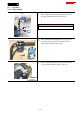


Table Of Contents
- 1 CONTENTS
- 2 CAUTION
- 3 NECESSARY REPAIRING TOOLS
- 4 FASTENING TORQUE
- 5 LUBRICANT AND ADHESIVE APPLICATION
- 6 REPAIR
- 7 CIRCUIT DIAGRAM
- 8 WIRING DIAGRAM

8 / 41
6-4 Switch box
6-4-1 Disassembling
Fig. 9
1
Remove M8x20 Hex bolt [1] and M8x40 Collar bolt [2].
Then pull off Handle R [4] from Sub frame [3].
Tips
Prepare a workbench or a box to put Handle R [4].
Fig. 10
2
Remove Binding PT 3x16 Tapping screw [1] (5 pcs) and
open Switch box L [2]. Electric parts can be removed
without disassembling Switch box R [3].
Fig. 11
3
Remove Switch [1] pushing lock of receptacle [2] with a
slotted screwdriver. This Receptacle is with lock.
[1]
[2]
[3]
[3]
[4]
[2]
[1]
[1]
[2]
Slotted
screwdriver