
Installation Guide

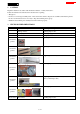


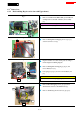


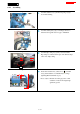

Table Of Contents
- 1 CONTENTS
- 2 CAUTION
- 3 NECESSARY REPAIRING TOOLS
- 4 FASTENING TORQUE
- 5 LUBRICANT AND ADHESIVE APPLICATION
- 6 REPAIR
- 7 CIRCUIT DIAGRAM
- 8 WIRING DIAGRAM

5 / 41
6 REPAIR
6-1 Battery
6-1-1 Disassembling
1 Remove Battery from the machine before repair.
6-2 Frame
6-2-1 Disassembling
Fig. 1
1
Release Rock lever [1].
2
Loosen M8x25 Thumb screw [3] (4pcs) and remove Spring
washer 8 [4], Flat washer 8 [5], M8x50 Hex bolt [6],
M8x75 Hex bolt [7] (2pcs) and then remove Frame [2].
Fig. 2
3
Upper frame [3] can be disassembled from Lower frame [5]
as follows.
4
Attach a Monkey wrench [8] to M16 x 24 Hex nut [7] to
lock and then remove M16 x 50 Hex bolt [1] with a socket
[9] and Impact Driver. (left/right both sides)
5
The components are as follows.
・ Flat washer 17 [2] (2pcs)
・ Sleeve 17 [4] (Apply lubricant to when assembling)
・ Spring washer 16 [6]
[1]
[2]
[7]
[6]
[3]
[4]
[5]
[1]
[4]
[3]
[5]
[2]
[6]
[8]
[9]
[3]
[5]
[3]
[5]
[7]