
Installation Guide

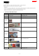


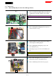


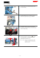

Table Of Contents
- 1 CONTENTS
- 2 CAUTION
- 3 NECESSARY REPAIRING TOOLS
- 4 FASTENING TORQUE
- 5 LUBRICANT AND ADHESIVE APPLICATION
- 6 REPAIR
- 7 CIRCUIT DIAGRAM
- 8 WIRING DIAGRAM

9 / 41
6-4-2 Assembling
Fig. 12
1
Assemble Switch lever [1] and Torsion spring 11 [2] as
shown in the left Fig.
Fig. 13
2
Assemble Switch plate [1] by connecting Connector to
Switch box through the bottom of pipe of Handle R.
Fig. 14
3
Assemble Pipe clamp 28 [1] if they are disassembled.
Pipe clamp is non-directional in spite of the different shape
of the ends of Pipe clamp.
Fig. 15
4
Insert a Hex wrench 4 into yellow arrow ( ) of Switch
box[1] and fit Switch box to Handle R by loosening/
tightening M5x16 S.H. Bolts (2 pcs).
How to adjust: 1.Distance from Grip [2] end: 0 -
3mm
2.Switch box must be fixed right angle
against the ground.
[1]
[1]
[2]
[1]
[2]
[1]
[2]
0 - 3mm