
User's Manual


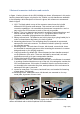


Table Of Contents

2 External connectors indicators and controls
In figure 1, below, pictures of the HDR-160MHz are shown. All antennas in this series
have the same basic layout, only that for the 750MHz, no-side handles are available.
In the following a brief description of the unit is given, with reference to arrows and
labels in figure
1. GPS. The black plastic on top of the connector tower hoses the in-build
differential GPS-receiver and antenna. This receiver has in-built SBAS-
correction capabilities. It is essential that the antenna is mounted in a such a
way to give the GPS antenna as much of free sky as possible
2. Battery. The LI-Ion batteries are housed in a casing of worked aluminum, and
have a nominal capacity of 7.8 Ah, 11.1V. This gives at least 5 hours of
operation, somewhat varying between the different models.
3. Battery release knob. The batteries are held in place by a spring loaded pin, in
order to release/mount the battery, the knob is pulled.
4. Measuring wheel mount. The measuring wheel is mounted via a protected,
waterproof 9-oin d-sub connector. The wheel is locked in place by a vertical
pin, see later section.
5. Mounting inserts. The units have 2 inserts, M6-threads, on each side, these
are intended for mounting purposes, either mounting the antenna in a custom-
designed carrier or for carrying purposes.
6. Carrying handles. By default the 3 lower frequencies have handles mounted
on the perimeter of the units. These are intended for tunnel wall, rock-wall
applications as well as for pure transportation handles.
7. Product label and LED-indicators see later sections.
8. Connection tower. Power, communications as well as on/off button is mounted
in a casing of worked aluminum on top of the unit; this casing also contains the
GPS unit and antenna, if this option is installed. Note the connection tower is
not intended to be removed at any time, waterproofness of the unit cannot be
warranted if this part is removed.
9. Inserts for wear-plate. Two inserts, back and front, are intended for fastening
of wear plates, M4-threads.
10. Mounting inserts. Additional inserts, M6-threads, are mounted on the top
metal plate, by means of insert-rivets.
Figure 1, pictures from back (left), and front (right) of the HDR-160MHz antenna,
arrows and labels refer to items explained in the text above.
1
2
3
4
5
6
7
8
9
10
Page 7 (16)