F18 WARRIOR 1 05/01
PREMESSA •Il d’officina, contempla le principali verifiche elettro/meccaniche, i controlli indispensabili ed il Il presente manuale d’officina montaggio di componenti forniti sfusi, per effettuare la consegna del motociclo nuovo di fabbrica (la sequenza delle operazioni, non è impegnativa). •È È molto importante attenersi scrupolosamente a quanto descritto. Interventi superficialmente eseguiti o addirittura omessi, possono generare danni personali all’acquirente, al motociclo, ecc...
NOTE DI CONSULTAZIONE HINWEISE ZUM NACHSCHLAGEN NOTES FOR EASY CONSULTATION NOTES POUR LA CONSULTATION NOTAS DE CONSULTA A C ONOSCERE LA MOTO KENNTNIS DES MOTORROLLERS GETTING TO KNOW THE MOTOR-BIKE CONNAITRE LA MOTO CONOCER LA MOTO B REGOLAZIONI MECCANICHE MECHANISCHE EINSTELLUNGEN MECHANICAL ADJUSTMENTS REGLAGES MECANIQUES REGULACIONES MECANICAS C SCOMPOSIZIONE GENERALE ALLGEMEINE DARSTELLUNG GENERAL BREAKDOWN DECOMPOSTION GENERALE DESMONTAJE GENERAL D COMPONENTI ELETTRICI ELEKTRO
ATTENZIONE! Consigli prudenziali ed informazioni riguardanti la sicurezza del motociclista (utente del motoveicolo) e la salvaguardia dell’integrità del motoveicolo stesso. ACHTUNG! Ratschläge und Informationen betreffend die Sicherheit des Kradfahrers (des Kraftradbenutzers)und die Unversehrtheit des Motorrollers selbst. CAUTION! Recommendations and precautions regarding rider safety and motor vehicle integrity.
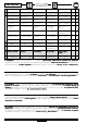
F18 125/150 PRECONSEGNA - EINGRIFFE PRE-DELIVERY - AVANT LIVRAISON - ANTES DE LA ENTREGA N° INTERVENTO EINGRIFF INTERVENTION INTERVENTION INTERVENCION S P Auspacken Unpacking Décaissement Controllo estetico Sichtkontrolle Aesthetic control Contrôle esthétique Control “estético” A 13 Controllo dati identificazione Kontrolle der Data control Identifikationsdaten identification Contrôle des données Control datos de d’identification identificación A 14 Kritische Befestigungen Critical ti
F18 125/150 N° INTERVENTO 5 Controlli vari EINGRIFF INTERVENTION INTERVENTION Verschiedene Kontrollen Various controls Pressione pneumatici Reifendruck INTERVENCION S P Contrôles divers Controles varios Tyres pressure Pression pneus Presión neumáticos A 28 Arranque A 24 Avviamento Anlassen Starting Démarrage Bloccasterzo Lenkersperre Steering lock Verrou de direction Seguro de dirección A 20 Comandi al manubrio Bedienungselemente Handlebar controls Commandes sur le guidon Ma
F18 125/150 S INDICE CONTENTS SOMMAIRE ÍNDICE P Dati tecnici Technische Daten Technical Data Caract.
F18 125/150 S B INDICE INHALT SOMMAIRE ÍNDICE P Regolazione minimo Regelung der Leerlaufdrehzahl Idle tuning Réglage ralenti Ajuste ralentí 1 Ammortizzatori Stoßdämpfer Shock absorbers Amortisseurs Amortiguadores 2 Verifica dei serraggi Prüfung der Anzugsmomente Tightening check Contrôle des serrages Control puntos de apriete 3 Sterzo Lenkung Steering Direction Manillar 4 Body Fairings Carrosserie Composition des carénages Carrocería Composición de los carenados 3 Carrozze
F18 125/150 S INDICE INHALT CONTENTS ÍNDICE P Rimozione paragambe Ausbau des Beinschilds Leg fender removal Dépose du tablier avant Desmontaje de la protección para las piernas Rimozione pedana appoggiapiedi Abmontieren des Trittbrettes Footboard removal Levée du repose-pied Desmontaje plataforma reposapiés Fuel tank removal Dépose du réservoir Desmontaje depósito du carburant de gasolina 35 Exhaust pipe removal Dépose pot d’échappement 38 Rimozione serbatoio Ausbau des carburante Benz
F18 125/150 S INDICE INHALT Rimozione leveraggio Ausbau der Hebelei Verifica dimensionale del telaio CONTENTS SOMMAIRE ÍNDICE P Dépose des leviers Desmontaje grupo palancas 76 Kontrolle der Rah- Dimensional menabmessungen frame check Contrôle dimensionnel du cadre Comprobación de las dimensiones del chasis 77 Lampade del faro anteriore Lampen des vorderen Headlight Scheinwerfers bulbs Ampoules du feu avant Luces del faro delantero 0 Regolazione fascio luminoso Regelung des Lichtbündel
A F18 125/150 DATI TECNICI CARATTERISTICHE GENERALI Passo Lunghezza Larghezza Altezza max.
A F18 125/150 TELAIO Monotrave in tubolare d’ acciaio, sdoppiato all’altezza della pedana SOSPENSIONI Anteriore: forcella oleodinamica, telescopica Steli Corsa Posteriore: n° 2 ammortizzatori idraulici con precarica molla regolabile Corsa FRENI Anteriore: a disco, con trasmissione oleodinamica a 3 pistoncini (sistema integrale) Posteriore: a disco con trasmissione oleodinamica a 2 pistoncini (sistema integrale) IMPIANTO ELETTRICO Batteria Generatore: volano alternatore Proiettore anteriore con lampada al q
A F18 125/150 DISIMBALLO •Disimballare il motociclo attenendosi alle indicazioni fornite sull’imballo stesso che dovrà essere poi smaltito, in conformità alle normative vigenti. CONTROLLO “ESTETICO” •Verificare visivamente il corretto montaggio di tutti i componenti in materiale plastico e contemporaneamente, la totale assenza di graffi, segni, ecc... su ogni parte dello scooter. AUSPACKEN UNPACKING •Das Kraftrad unter Befolgung der auf der Verpackung geschilderten Anweisungen auspacken.
A F18 125/150 DATI PER L’IDENTIFICAZIONE TELAIO - I dati per l’identificazione del telaio, sono punzonati sulla parte posteriore destra del telaio, nella zona (A - F. 1). M O T O R E - I dati per l’identificazione del motore, sono visualizzabili nella parte inferiore sinistra, del motore stesso (B - F. 2). IDENTIFIKATIONSDATEN IDENTIFICATION DATA R A H M E N - Die Rahmenidentifizierungsdaten sind rechts auf der Rahmenrückseite A - Abb.1 gestempelt (A Abb.1) .
A F18 125/150 IDENTIFICAZIONE ELEMENTI PRINCIPALI (Lato destro ) destro) N. 1 13 14 Descrizione 1 Cruscotto 2 Serbatoio liquido di raffreddamento 3 Commutatore a chiave 4 Tappo serbatoio carburante 5 Vano porta casco 6 Batteria 7 Sella biposto 8 Fanalino posteriore 9 Porta targa 10 Marmitta 11 Cavalletto centrale 12 Gancio antifurto 13 Specchio retrovisore sinistro 14 Specchio retrovisore destro 6 7 5 2 4 3 8 9 12 10 11 F.
A F18 125/150 IDENTIFICAZIONE ELEMENTI PRINCIPALI (Lato sinistro ) sinistro) N. Descrizione 15 Faro anteriore 16 Indicatori di direzione (ant.) 17 Serbatoi olio freni (post.) 18 Radiatore 19 Pinza freno a disco (ant.) 20 Forcella 21 Pedivella avviamento 22 Filtro aria 23 Carburatore 24 Candela 25 Ammortizzatori regolabili 26 Serratura sella 17 26 25 16 15 23 22 20 21 24 18 19 F.4 KENNZEICHNUNG DER HAUPTELEMENTE (Linke Seite) IDENTIFICATION OF MAIN COMPONENTS (Left side) No.
A F18 125/150 COMANDI AL MANUBRIO Comando destro A A) Serbatoio olio freno anteriore B) Leva freno anteriore C) Manopola acceleratore B 1) 2) Pulsante avviamento elettrico. Interruttore luci: 2 a destra = spento C posizione centrale = luci di posizione e cruscotto 1 a sinistra = luci anabbaglianti. 3) Contrappeso dx. 3 F.
A F18 125/150 COMANDI AL MANUBRIO Comando sinistro A 4 A) Serbatoio olio freno posteriore B) Leva freno posteriore B 1) 2) 3) 4) 5) Pulsante avvisatore acustico. Disinnesco indicatori di direzione Interruttore indicatori di direzione Deviatore luci: abbaglianti anabbaglianti. Contrappeso sx. 3 1 5 F.
A F18 125/150 INTERRUTTORE DI AVVIAMENTO/CHIAVI •L’interruttore principale (F. 7) controlla il circuito d’avviamento, il dispositivo bloccasterzo. : ogni contatto elettrico è disinserito o. : sono inseriti i contatti ed il motore può avviarsi. AVVIAMENTO: girare la chiave in senso orario e azionare una delle due leve freno quindi premere il pulsante di starter. :inserimento bloccasterzo. F.7 F.8 ANLASSSCHALTER/SCHLÜSSEL STARTER/KEYS •Der Hauptschalter (Abb.
A F18 125/150 CHIAVI Il veicolo è fornito di due chiavi con codice numerico, le quali consentono di: • Stabilire il contatto di avviamento. • Bloccare lo sterzo. • Accedere al vano porta-casco. • Aprire lo sportellino del paragambe. BLOCCASTERZO Inserimento Col manubrio sterzato a sinistra, inserire a fondo la chiave e successivamente ruotarla in senso antiorario (F. 9). Disinserimento Ruotare la chiave in senso orario. F.
A F18 125/150 CAVALLETTO CENTRALE •La posizione del cavalletto centrale (1 - F. 10), non é controllata elettronicamente, é quindi possibile l’avviamento del motore con il motociclo in stazionamento. •Verificare il corretto fissaggio e la mobilità del cavalletto centrale. •Controllare inoltre il corretto ancoraggio delle molle di richiamo (A - B).
A F18 125/150 CAVALLETTO LATERALE (OPTIONAL) •La posizione del cavalletto laterale (1 - F. 11), non è controllata da alcun dispositivo elettronico, é comunque vivamente sconsigliabile avviare il motore con il motociclo parcheggiato sul cavalletto laterale. •Verificare il corretto fissaggio e la mobilità del cavalletto laterale. •Controllare inoltre il corretto ancoraggio delle molle di richiamo (A - B).
A F18 125/150 CRUSCOTTO 1) 2) 3) 4) 5) 6) Indicatore temperatura liquido refrigerante. La zona “rossa” (A) evidenzia una temperatura eccessiva dovuta a funzionamento anomalo. Indicatore livello carburante. La spia (B) indica l’entrata in riserva. Tachimetro (numeri bianchi: km - numeri rossi: miglia) e contachilometri. Spia (verde) luci anabbaglianti. Spia (blu) luci abbaglianti. Spia (verde) indicatore di direzione. 2 3 A 1 B 4 5 6 F.
A F18 125/150 AVVIAMENTO ELETTRICO • Posizionare lo scooter sul cavalletto centrale. • Inserire la chiave d’avviamento nell’interruttore e ruotarla in posizione . • Tirare una delle due leve dei freni (preferibilmente quella inerente il freno posteriore). • Premere il pulsante d’avviamento. • Rilasciare il pulsante d’avviamento non appena il motore si avvia. • Liberare il cavalletto e sedersi sulla sella.
A F18 125/150 AVVIAMENTO A PEDALE • Per avviare il motore con la pedivella: - mettere il veicolo in appoggio sul cavalletto, estrarre (ruotare verso l’esterno) con la mano, la leva (A) della pedivella. - Tenere entrambe le mani sul manubrio. Con la mano sinistra mantenere tirata la leva del freno posteriore evitando così che lo scooter possa muoversi. Con la mano destra impugnare la manopola dell’acceleratore, senza ruotarla per non ingolfare il motore durante l’avviamento.
A F18 125/150 AVVIAMENTO A MOTORE FREDDO Per l’avviamento a freddo, non intervenire (per i primi tentativi) sulla manopola dell’acceleratore, essendo il motore provvisto di un dispositivo di starter automatico che, durante i minuti iniziali di funzionamento, produrrà un regime digiri più elevato elevato. Non salire sullo scooter parcheggiato sul cavalletto. 1) Ruotare la chiave di accensione in senso orario in posizione . 2) Chiudere completamente la manopola dell’acceleratore.
A F18 125/150 INCONVENIENTI DI FUNZIONAMENTO IL MOTORE NON VA IN MOTO 1) Leva freno non azionata: •azionare una delle leve freno. 2) Interruttore principale non attivato: •inserire la chiave e ruotarla in senso orario. 3) Corpo carburatore, getto o rubinetto ostruito 4) Motore ingolfato: • aprire tutto il gas ed insistere nella messa in moto, oppure smontare ed asciugare la candela prima di avviare il motore. • Verificare la tenuta dello spillo valvola del galleggiante.
A F18 125/150 PNEUMATICI TUBELESS CONTROLLO PRESSIONE La pressione dei pneumatici deve essere controllata gomma fredda e regolata a “gomma fredda”. X 110/70 - 13’’ 57L Y 130/60 - 13’’ 57L F. 16 Kg/cm2 X 2,0 2,0 Y 2,0 2,1 SCHLAUCHLOSE REIFEN TUBELESS TYRE DRUCKKONTROLLE PRESSURE CONTROL Der Reifendruck muß bei “kaltem Gummi Gummi”kontrolliert und reguliert werrden. Wheel pressure has to be controlled and regulated cold when tyres are “cold cold”.
A F18 125/150 SERBATOIO CARBURANTE Per accedere al tappo del serbatoio carburante, posto sotto la sella, procedere come segue: • Posizionare lo scooter sul cavalletto centrale. • Estrarre la chiave d’accensione ed inserirla nella serratura (1) della sella, quindi ruotarla in senso antiorario. • Sollevare la sella completamente e svitare il tappo (2) del serbatoio carburante.
A F18 125/150 SERBATOIO LIQUIDO REFRIGERANTE KÜHLMITTELTANK • Il serbatoio del liquido refrigerante preposto al raffreddamento del motore è accessibile aprendo con la chiave di accensione, il portello (A - F. 18) posto sul paragambe. • Der Kühlmitteltank zur Kühlung des Motors ist nach der Öffnung der Beinschutzklappe (A - Abb.18) mit dem Anlass-Schlüssel erreichbar.
A F18 125/150 COOLANT TANK •The coolant tank for the engine cooling is accessible by opening the leg-guard door (A - F. 18) by means of the starting key. • Filling with coolant is to be carried out using the product type recommended in this handbook or an equivalent one. • Never fill with water. COOLANT •Check the coolant level with cold engine. •In order to check the coolant level, place the motorcycle on the central stand (flat) and look at the tank (1 - F. 19) from the bottom (F.
A F18 125/150 OLIO MOTORE MOTORENÖL Controllo livello • Posizionare lo scooter sul cavalletto centrale e scaldare il motore per qualche minuto. • Arrestare il motore e attendere qualche minuto, affinché il livello olio si stabilizzi, prima di controllare. • Svitare dal carter motore, l’asticella di misurazione (A - F. 21). • Pulire l’asticella e reinserirla nella sua sede, senza avvitarla. Questa operazione consente di verificare il livello dell’olio.
A F18 125/150 ENGINE OIL HUILE MOTEUR ACEITE MOTOR Level check •Place the scooter on the central stand and warm up the engine for some minutes. •Stop the engine and wait some minutes till the oil level settles, then check. •Unscrew the dipstick (A - F. 21) from the engine case. •Clean it and place it again in its seat without screwing it. Oil level can thus be checked. •The level should be between the MIN. and MAX. marks on the dipstick (F. 21). If it is too low, fill with oil.
A F18 125/150 GETRIEBEÖL OLIO TRASMISSIONE Controllo livello • Posizionare lo scooter in piano, sul cavalletto centrale. • Rimuovere la vite d’ispezione (V - F. 22) e verificare che l’olio lambisca la parte inferiore del foro. • Se necessario, rabboccare con olio: Q8 T35 - 80W procedendo come segue: • inserire nel foro di controllo, un tubetto (A - F. 23) solidale ad un normale imbuto (B). C • Versare con cautela l’olio all’interno dell’imbuto, fino a verificare un leggero sgocciolamento dal F.
A F18 125/150 TRANSMISSION OIL HUILE DE TRANSMISSION ACEITE TRANSMISION Level check •Place the scooter flat on the central stand. •Remove the inspection screw (V - F. 22) and check if oil reaches the hole lower part. •If necessary, fill with oil: Q8 T35 - 80W following these operations: •fit a tube (A - F. 23) forming an integral part with a common funnel (B) in the inspection hole. •Pour oil with care in the funnel till drops come out of the inspection/inlet hole.
A F18 125/150 OLIO FRENI ANTERIORE POSTERIORE ÖL FÜR VORDER- UND HINTERRADBREMSE Controllo • Il controllo (visivo) va effettuato attraverso la spia (S) dei serbatoi: A - F. 24 (freno anteriore) B - F. 25 (freno posteriore), con lo scooter in piano e perfettamente verticale. • Il livello è corretto quando il fluido risulta a 3 mm dal limite inferiore della spia. • I rabbocchi vanno effettuati rimuovendo i coperchi .
A F18 125/150 FRONT AND REAR BRAKE OIL HUILE DES FREINS AVANT ET ARRIERE ACEITE FRENOS DELANTERO Y TRASERO Check •Visual check is to be performed through the tank window (S): A - F. 24 (front brake) B - F. 25 (rear brake), while the scooter is in uprightlevelled position. •Oil level is correct when the liquid is 3 mm over the lower limit of the window. •Filling is to be carried out after having removed the covers (A - B) and unscrewed both securing screws (V2). Recommended oil: Q8 BRAKE FLUID DOT 4 4.
A LUBRIFICANTI OLIO MOTORE (4 TEMPI) SCHMIERMITTEL MOTORÖL (VIERTAKT) LUBRICANTS (4 STROKE CYCLE) ENGINE OIL LUBRIFIANTS LUBRICANTES HUILE MOTEUR (4 TEMPS) ACEITE MOTOR (4 TIEMPOS) HUILE TRANSMISSION MOTEUR ACEITE TRANSMISION MOTOR LUBRIFIANT POUR FILTRESAAIR LUBRICANTEPARAFILTROSDEAIRE LIQUIDE RADIATEUR LIQUIDO RADIADOR LUBRIFIANT CIRCUIT DE FREINAGE LUBRICANTECIRCUITODEFRENADO CLASS SAE 10W - 40 OLIO TRASM. MOTORE ÖL MOTORGETRIEBE ENGINE TRANSMISSION OIL T35 - 80W LUBR.
B F18 125/150 REGOLAZIONE DEL MINIMO •Per accedere al carburatore occorre rimuovere il vano porta casco (vedi S/C - P. 24 24) . •Per effettuare una corretta verifica del regime minimo, avviare il motore e mantenerlo lievemente accelerato, (almeno 3 minuti) fino al raggiungimento della temperatura di normale funzionamento, quindi lasciarlo al “minimo” verificandone il regime di rotazione. •La regolazione del minimo si ottiene agendo sulla vite (V).
B F18 125/150 AMMORTIZZATORI REGOLAZIONE •Gli ammortizzatori posteriori dispongono di regolazione sul precarico della molla. La regolazione si effettua intervenendo con l’apposita •La chiave in dotazione sulla ghiera inferiore (A - F. 2), ruotandola nel senso indicato dalla freccia (vedi figura) si aumenta la forza della molla (quindi maggiore carico trasportabile). A Nota: sono previste tre posizioni di regolazione: 1) “Morbida” - solo conducente - carico minimo - percorsi accidentati - ecc...
B MADISON F18 125/150 250 VERIFICA DEI SERRAGGI •In occasione della preconsegna, e durante i “tagliandi”, verificare il corretto serraggio degli ammortizzatori posteriori. •Fissaggio Fissaggio superiore: dadi (B - F. 3) •Fissaggio Fissaggio inferiore: viti (V2 - F. 4) KONTROLLE DER BEFESTIGUNG TIGHTENING CONTROLS •Vor der Übergabe des Motorrades und währen der “Kupon” Kontrollen, die Befestigung der hinteren Stoßdämpfer kontrollieren.
B F18 125/150 A STERZO Cs - Nm 140 CONTROLLO DEL GIOCO •Posizionare il motociclo su cavalletto centrale. •Ruotare il manubrio ripetutamente nei due sensi, valutando il grado di scorrevolezza delle sfere. •Riscontrando resistenza alla rotazione (anche lieve) o eccessiva scorrevolezza, procedere alla regolazione utilizzando l’apposita chiave. A B REGOLAZIONE Nota: per accedere alle ghiere di regolazione dello sterzo, è necessario rimuovere lo scudo anteriore (vedi S/C - P. 5 5) .
B F18 125/150 C CONTROLLO “SERRAGGIO” MANUBRIO •Verificare il corretto serraggio del dado (C - F. 6). Cs - Nm 50 C F.6 KONTROLLE DER LENKER- “BEFESTIGUNG” •Kontrollieren Sie, dass die Schraubenmutter (C - Abb. 6) richtig befestigt ist. HANDLEBAR “TIGHTENING” CONTROL •Control the correct tightening of the nut (C - F. 6). CONTROLE “SERRAGE” GUIDON •Vérifier le bon serrage de l’écrou (C - F. 6). CONTROL “APRIETE” DEL MANILLAR •Comprobar que la tuerca (C - F. 6) esté correctamente apretada.
NOTE HINWEIS NOTES NOTES NOTAS ............................................................................................................................................................................................................................................ ............................................................................................................................................................................................................................................ ..
CC F18 125/150 Nota - In questa sezione sono riportate tutte le descrizioni necessarie allo smontaggio e rimontaggio dei principali componenti del motociclo. Per la complessità di alcune procedure e per l’assoluta necessità di mantenere in ogni condizione, il motociclo perfettamente stabile ed in posizione razionale per l’operatore, si consiglia vivamente di utilizzare un “ponte” di sollevamento (F.1) provvisto dei dispositivi di sicurezza previsti dalle normative vigenti.
C F18 125/150 6 5 1 2 9 8 11 3 12 10 15 14 16 13 4 5 6 7 1 9 11 2 8 12 3 15 14 4 16 13 F.
C F18 125/150 CARROZZERIA KAROSSERIE COMPOSIZIONE DELLE CARENATURE AUFBAU DER SEITENVERKLEIDUNGEN BESCHREIBUNG Oberschild Frontschutzplatte Schutzblech vorne Schutzblech Frontschutzplatte Lenkerverkleidung vorne Lenkerverkleidung hinten Rahmen Armaturenbrett Beinschutz Heckverkleidung Schutzblech hinten Kennzeichenschildträger Spritzblech Fußbrett Tunneldeckel Heck Strebe N° DESCRIZIONE 1 Scudo superiore 2 Scudo 3 Parafango anteriore 4 Parafango sottoscudo 5 Coprimanubrio anteriore 6 Coprimanubrio pos
C F18 125/150 MONTAGGIO TARGA (Operazione di pre-consegna) Nota: lo scooter viene fornito con il porta targa. Il montaggio della targa è a cura del Concessionario. A A •Montare la targa sul relativo supporto (1) fissandola sulle asole (A) con viti, oppure rivetti. 1 Non utilizzare collanti, nastri biadesivi, ecc... per il fissaggio della targa. F.
C F18 125/150 RIMOZIONE SCUDO SUPERIORE Nota - Per rimuovere lo scudo superiore (1 - F. 4) procedere come segue: •Svitare le viti autofilettanti (V2 - F. 5). ENTFERNUNG DES OBERSCHILDES REMOVING THE UPPER SHIELD Anmerkung - Vorgehensweise zur Entfernung des Oberschildes (1 - Abb. 4): Note - Following operations have to be carried out to remove the upper shield (1 - F. 4): •Die selbstschneidenden Schrauben ausschrauben (V2 - Abb. 5). •Unscrew the self-tapping screws (V2 - F. 5).
C F18 125/150 •Inserire un cacciavite (a punta piatta) o altro utensile simile, nella fessura di separazione dello scudo superiore (1 - F. 6) e dello scudo (2). 1 •Einen Schraubenzieher (oder ein ähnliches Werkzeug) in den Trennungsspalt des Oberschilds (1 - Abb. 6) und des Schilds (2) einstecken. 2 F.6 •Mit höchster Sorgfalt, nach der Befreieung der Feder (3 - Abb. 7) den Oberschild heben. •Con estrema cautela,fare leva e sollevare lo scudo superiore liberando le linguette d’incastro (3-F.7). 3 F.
C F18 125/150 •Insert a screwdriver (flat-type) or an equivalent tool into the separating slit of the upper shield (1 - F. 6) and of the shield (2). •Introduire un tournevis (plat) ou un autre outil semblable dans la fente de séparation du bouclier supérieur (1 - F. 6) et du bouclier (2). •Introducir un desatornillador (de punta plana) u otra herramienta similar, en la fisura de separación situada entre el escudo superior (1 - F. 6) y el escudo (2).
C F18 125/150 POSSIBILITÀ DI ACCESSO CON LA RIMOZIONE DELLO SCUDO SUPERIORE MÖGLICHE EINGRIFFE NACH DER ENTFERNUNG DES OBERSCHILDES Nota - La rimozione dello scudo superiore, consente li seguenti interventi: Anmerkung - Durch die Entfernung des Oberschildes sind folgende Eingriffe möglich: •Sostituzione lampade del faro. •Ersatz der Scheinwerferlampen. •Sostituzione lampade dei segnalatori di direzione (F. 9). •Ersatz der Richtungsanzeigerlampen (Abb. 9). F.9 •Entfernung der Hupe (Horn - 1 - Abb.
C F18 125/150 POSSIBLE OPERATIONS AFTER THE UPPER SHIELD REMOVAL POSSIBILITE D’ACCES APRES LA LEVEE DU BOUCLIER SUPERIEUR POSIBILIDAD DE ACCESO QUITANDO EL ESCUDO SUPERIOR Note - Removing the upper shield, following operations may be carried out: Note - enlever le bouclier supérieur permet de réaliser les interventions suivantes : Nota -Tras quitar el escudo superior se podrán efectuar las siguientes intervenciones: •Headlight lamp replacement.
C F18 125/150 RIMOZIONE COPRIMANUBRIO ANTERIORE ENTFERNUNG DER VORDEREN LENKERABDECKUNG •Svitare la vite centrale (V1 - F.12). •Die Mittelschraube losschrauben (V1 - Abb.12). V1 F. 12 •Svitare le viti laterali, inferiori (V2 - F. 13). •Die seitlichen unteren Schrauben losschrauben (V2 - Abb. 13). V2 F. 13 •Svitare le viti posteriori (V2 - F. 14). •Die Hinterschrauben losschraube (V2 - Abb. 14). V2 F. 14 •Estrarre dall’alto il coprimanubrio completo di cruscotto (F.
C F18 125/150 REMOVING THE FRONT HANDLEBAR COVER LEVEE DU PROTEGE-GUIDON AVANT DESMONTAJE CUBREMANILLAR DELANTERO •Unscrew the central screw (V1 - F. 12). •Dévisser la vis centrale (V1 - F.12). •Aflojar el tornillo central (V1 - F.12). •Unscrew the lower side screws (V2 - F. 13). •Dévisser les vis latérales inférieures (V2 - F. 13). •Aflojar los tornillos laterales, inferiores (V2 - F. 13). •Unscrew the rear screws (V2 - F. 14). •Dévisser les vis arrière (V2 - F. 14).
C F18 125/150 RIMOZIONE CRUSCOTTO ENTFERNUNG DES ARMATURENBRETTS Nota - Il gruppo cruscotto viene rimosso insieme al coprimanubrio anteriore. Anmerkung - Die Gruppe des Armaturenbretts wird zusammen mit der vorderen Lenkerabdeckung entfernt. A B A F. 16 •Mit den Fingern auf die Laschen (A - Abb.16) drücken und das Transmissionskabel des Kilometerzählers von unten herausziehen (B - Abb. 17). •Premere con le dita sulle linguette (A - F.
C F18 125/150 REMOVING THE DASHBOARD LEVEE DU TABLEAU DE BORD DESMONTAJE TABLERO DE INSTRUMENTOS Note - The dashboard unit is to be removed together with the front handlebar cover. Note - Le groupe tableau de bord s’enlève avec le protège-guidon avant. Nota - El grupo tablero de instrumentos se desmonta junto con el cubremanillar delantero. •Press on the tongues (A - F. 16) with the fingers and withdraw the transmission cable of the odometer (B - F. 17) from the bottom.
C F18 125/150 POSSIBILITÀ DI ACCESSO CON LA RIMOZIONE DEL COPRIMANUBRIO ANTERIORE Nota - La rimozione del coprimanubrio anteriore e cruscotto, consente l’accesso ai seguenti componenti: •Cablaggio cruscotto (A) •Cablaggio cruscotto (B) •Connettore cavo trasmissione contachilometri (C) •Connettore dei comandi al manubrio (destro) (D) •Connettore dei comandi al manubrio (sinistro) (E) •Interruttore STOP comando destro (F) •Interruttore STOP comando sinistro (G) •Raccordo per pompa freno posteriore (H) •Racco
C F18 125/150 SOSTITUZIONE LAMPADE DEL CRUSCOTTO •Nella configurazione di figura 21, è possibile sostituire le lampade del cruscotto, A-B-C-D-E-F-G-H. Nota - È consigliabile provare il corretto funzionamento della lampada sostituita, prima di rimontare il cruscotto (coprimanubrio) e fissarlo definitivamente. SEPARAZIONE DEL CRUSCOTTO DAL COPRIMANUBRIO ANTERIORE •Svitare le viti (V4 - F. 21) ed estrarre il cruscotto (1).
C F18 125/150 RIMOZIONE COMANDI AL MANUBRIO •Per rimuovere i dispositivi dei due comandi elettrici, posti sul manubrio, occorre rimuovere il coprimanubrio superiore per accedere ai connettori elettrici (A - B - F. 22). A •Svitare le viti (V2). •Separare con cautela le due semi unità, componenti il dispositivo. •Nel rimontaggio, serrare le viti (V2) alla coppia indicata. V2 B F.
C F18 125/150 RIMOZIONE RUOTA ANTERIORE Verificare la perfetta stabilità del motociclo. •Con l’ausilio di una pinza, svitare il terminale (A - F. 23) del cavo di trasmissione contachilometri. A F. 23 ENTFERNUNG DES VORDERRADS REMOVING THE FRONT WHEEL Die vollkommene Standfestigkeit des Motorrollers prüfen. Check the motorcycle perfect stability. •Mit einer Zange, den Endverschluß (A - Abb. 23) des Transmissionskabels des Kilometerzählers ausschrauben.
C F18 125/150 •Svitare il dado (A - F. 24) di fissaggio perno ruota, trattenendo la testa del perno stesso, con una chiave esagonale. A Cs - Nm 45 ± 15% •Die Befestigungsmutter (A - Abb. 24) des Radzapfens ausschrauben. Den Kopf des Radzapfens mit einer Sechskantenschlüssel halten. •Sfilare il perno ruota prestando attenzione al rasamento (1 - F. 25). •Den Radzapfen herausziehen ohne die Zwischenlegscheibe zu beschädigen (1 - Abb. 25). •Separare il rinvio del contachilometri (2 - F. 26) dalla ruota.
C F18 125/150 •Unscrew the nut (A - F. 24) securing the wheel stud, holding the head of the wheel stud with a hexagonal wrench. •Dévisser l’écrou (A - F. 24) de fixation de l’axe de la roue tout en maintenant la tête de l’axe à l’aide d’une clef 6 pans. •Desenroscar la tuerca (A - F. 24) de fijación perno rueda, sujetando la cabeza del perno rueda con una llave hexagonal. •Withdraw the wheel stud paying attention to the shim (1 - F. 25). •Dégager l’axe de la roue en faisant attention au rasage (1 - F.
C F18 125/150 RIMOZIONE PARAFANGO ANTERIORE •Sfilare il cavo di trasmissione contachilometri (1 - F. 28). •Svitare le viti (V2 - F. 28) •Svitare le viti (V2a) ed i relativi dadi •Rimuovere il parafango (2) dalla parte anteriore, attraverso la forcella. V 2 Cs - Nm V 2//aa 3,5 ± 10% V2 1 2 V 2/a F. 28 ENTFERNUNG DES VORDEREN SCHUTZBLECHS REMOVING THE FRONT FENDER •Das Transmissionskabel des Kilometerzählers (1 - Abb. 28) herausziehen. •Die Schrauben (V2 - Abb. 28) ausschrauben.
C F18 125/150 RIMOZIONE SCUDO •Svitare le viti posteriori (V8). •Svitare le viti laterali (V2). ENTFERNUNG DES SCHILDES REMOVING THE SHIELD •Die hinteren Schrauben ausschrauben (V8). •Die seitlichen Schrauben ausschrauben (V2). •Unscrew the rear screws (V8). •Unscrew the side screws (V2). LEVEE DU BOUCLIER AVANT DESMONTAJE ESCUDO •Dévisser les vis arrière (V8). •dévisser les vis latérales (V2). •Aflojar los tornillos posteriores (V8). •Aflojar los tornillos laterales (V2).
C F18 125/150 •Divaricare lo scudo e scollegare i connettori del faro (F. 30). •Das Schild trennen und die Scheinwerferstecker ausschalten (Abb. 30). •Rimuovere lo scudo attraverso la forcella con cautela per non graffiarlo. •Riporre lo scudo capovolto, con la superficie verniciata, rivolta in alto. •Das Schild durch die Gabel mit Sorgfalt entfernen. •Das Schild umgeschlagen, mit der lackierten Oberfläche nach oben, stellen. F.
C F18 125/150 •Open the shield and disconnect the headlight connectors (F. 30). •Ecarter le bouclier et déconnecter les connecteurs du phare (F. 30). •Abrir el escudo y desconectar los conectores del faro (F. 30). •Remove with care the shield through the fork paying attention not to scratch it. •Place the shield upside down with its painted surface turned upwards.
C F18 125/150 RIMOZIONE VANO CASCO ENTFERNUNG DES HELMFACHES V2 •Ribaltare completamente in avanti, la sella. •Svitare le viti (V2 - F. 32) di fissaggio copribatteria (1). •Sollevare e rimuovere il copribatteria(1). •Den Sattel komplett nach vorne umkippen. •Die Schrauben (V2 - Abb. 32) zur Befestigung der Batteriedeckung (1) ausschrauben. •Die Batteriedeckung heben und entfernen (1). 1 F. 32 •Svitare la vite (A - F.
C F18 125/150 REMOVING THE HELMET COMPARTMENT LEVEE DU COFFRE À CASQUE DESMONTAJE HUECO PORTACASCOS •Turn the saddle completely forwards. •Unscrew the screws (V2 - F. 32) securing the battery cover (1). •Lift and remove the battery cover (1). •Basculer complètement la selle en avant. •Dévisser les vis (V2 - F. 32) de fixation du couvre-batterie (1). •Soulever et enlever le couvrebatterie (1). •Volcar el asiento completamente hacia adelante. •Aflojar los tornillos (V2 - F.
C F18 125/150 •Sollevare moderatamente il vano casco (1 - F. 36) e sfilare i cavi (A - B) della batteria. •Scollegare i quattro connettori.(C), collegati ai fusibili. 1 È consigliabile prendere appunti sulla sequenza di collegamento dei cavi per non commettere errori in fase di rimontaggio del vano casco. •Sollevare ed estrarre il vano casco. C A B F. 36 •Das Helmfach (1 - Abb. 36) leicht heben und die Kabel (A - B) der Batterie herausziehen.
C F18 125/150 RIMOZIONE “CODA” •Svitare le viti superiori (V4 - F. 37) •Svitare le viti laterali (V2 - F. 38) •Rimuovere la “coda” (1). ENTFERNUNG DES “HECKS” REMOVING THE “TAIL” •Die oberen Schrauben (V4 - Abb. 37) losschrauben •Die seitlichen Schrauben (V2 - Abb. 38) losschrauben •Das “Heck” entfernen (1). •Unscrew the upper screws (V4 - F. 37) •Unscrew the side screws (V2 - F. 38) •Remove the “tail” (1). LEVEE DE LA “QUEUE” DESMONTAJE “COLIN” •Dévisser les vis supérieures (V4 - F.
C F18 125/150 RIMOZIONE CARENATURA POSTERIORE Nota - Per rimuovere la carenatura posteriore (1 - F. 39) è necessario rimuovere preventivamente: S/C - P. 24 •Vano casco (compresa la sella) (S/C 24) S/C - P. 27 •“Coda” (S 7) •Fanale posteriore (S/D 0). S/D - P. 0 1 •Sollevare ed inclinare moderatamente la carenatura posteriore, per agevolarne la rimozione. F. 39 ENTFERNUNG DER HINTEREN VERKLEIDUNG REMOVING THE REAR FAIRING Anmerkung - Zur Entfernung der hinteren Verkleidung (1 - Abb.
C F18 125/150 RIMOZIONE PUNTONE Nota - Il puntone è diviso in due parti: anteriore e posteriore. •Preventivamente è necessario rimuovere il tappeto in gomma copripedana. (A - F. 40). RIMOZIONE PARTE POSTERIORE •Svitare le viti superiori (V4 - F. 40) •Svitare la vite centrale (V2 - F. 41) •Svitare la vite inferiore (V2/a - F. 41) •Rimuovere il carter (1). ENTFERNUNG DER STREBE REMOVING THE KICKSTAND Anmerkung - Die Strebe besteht aus zwei Teilen: Vorderund Hinterseite.
C F18 125/150 RIMOZIONE PARTE ANTERIORE •Svitare le viti (V4 - F. 42) •Estrarre il puntone prestando attenzione ai tubi di sfiato che lo attraversano: - Tubo destro (A - F. 43): sfiato serbatoio carburante - Tubo sinistro(A - F. 43): vaso espansione liquido refrigerante. ENTFERNUNG DER VORDERSEITE •Die Schrauben (V4 - Abb. 42) losschrauben. •Die Strebe herausziehen. Auf die Ablassröhre passen: - Rechtes Rohr (A - Abb. 43): Entlüftung Benzintank - Linkes Rohr (A - Abb. 43): Kühlmittel-Expansionsgefäß.
C F18 125/150 RIMOZIONE PARAGAMBE Nota - Per rimuovere il paragambe (1 - F. 44) è necessario rimuovere preventivamente lo scudo anteriore (S.C S.C - P. 21 21) . •Svitare le viti (V2) di fissaggio porta borsa. •Svitare le viti (V2/a - F. 45) per svincolare la pedana appoggiapiedi, dal paragambe. ENTFERNUNG DES BEINSCHUTZES REMOVING THE LEG-GUARD Anmerkung - Um den Beinschutz (1 - Abb. 44) zu entfernen, S.C - S. 21 ist der Vorderschild vorher zu entfernen (S.C 21) .
C F18 125/150 •Den Deckel (A - Abb. 46) des Schlüsselumschalters herausziehen. •Estrarre il coperchietto (A - F. 46) del commutatore a chiave. A F. 46 •Svitare e rimuovere il tappo del vaso di espansione liquido refrigerante (B) . •Den Verschluss des KühlmittelExpansionsgefäßes (B) ausschrauben und entfernen. B F. 47 •Die elektronische Steuereinheit befreien und entfernen (C - Abb. 48 - Abb. 49). •Sganciare e rimuovere la centralina elettronica (C - F. 48 - F. 49). C F.
C F18 125/150 •Remove the cover (A - F. 46) of the key switch. •Extraire le couvercle (A - F. 46) du démarreur à clef. •Quitar la tapa (A - F. 46) del interruptor de llave. •Unscrew and remove the coolant expansion (B) tank cap. •Dévisser et enlever le bouchon du réservoir d’expansion du liquide de réfrigération (B). •Desenroscar y quitar el tapón del recipiente de expansión líquido refrigerante (B). •Release and remove the electronic control unit (C - F. 48 - F. 49).
C F18 125/150 RIMOZIONE PEDANA APPOGGIAPIEDI Nota - Per rimuovere la pedana appoggiapiedi, è necessario rimuovere preventivamente: •Batteria (S.C S.C - P. 24 24) S.C - P. 24 24) •Vano casco (S.C •Scudo anteriore (S.C S.C - P. 5 5) •Paragambe (S.C S.C - P. 31 31) V2 •Svitare la vite (V2 - F. 50) •Rimuovere la pedana completa. F.
C F18 125/150 RIMOZIONE SERBATOIO CARBURANTE I vapori di benzina sono altamente tossici i, quindi nocivi alla salute. Aerare il locale prima di procedere e, se necessario, indossare una mascherina personale. Non rimuovere il serbatoio, se non è stato preventivamente completamente svuotato. Non fumare nè utilizzare fiamme libere. Effettuate tutte le operazioni in assenza assoluta di lavorazioni che producono scintille (saldature, smerigliature, ecc...).
C F18 125/150 Bei der Entfernung des Trittbretts und bei der Montage des Benzintanks prüfen, ob die Dämpfungspolster vorhanden sind (A - Abb. 51). Nella rimozione della pedana appoggiapiedi e nel rimontaggio del serbatoio carburante, verificare la presenza delle spugne antivibrazioni (A - F. 51). •Svitare la vite (V2 - F. 51) •Die Schraube (V2 - Abb. 51) losschrauben. V2 A F. 51 •Die Schraube (V - Abb. 52) losschrauben. •Svitare la vite (V - F. 52). V F. 52 •Mit einer Zange, die Schelle (B - Abb.
C F18 125/150 When removing the footboard and fitting again fuel tank, check the presence of the sponge damper pads (A - F. 51). Au moment d’enlever le tapis du repose-pied et de remonter le réservoir du carburant, vérifier la présence des éponges antivibrations (A - F. 51). Durante el desmontaje de la plataforma reposapiés y el remontaje del depósito de combustible verificar la presencia de las esponjas amortiguadoras de vibraciones (A - F. 51). •Unscrew the screw (V2 - F.
C F18 125/150 RIMOZIONE MARMITTA V3 Cs - Nm 42 ± 15% ABMONTIEREN DES AUSPUFFSCHALLDÄMPFERS Lasciare raffreddare opportunamente la marmitta. V3 Nota - Per rimuovere la marmitta, non è necessario rimuovere alcun elemento della carrozzeria. Den Auspuffschalldämpfer abkühlen lassen. Anmerkung - Zur Entfernung des Schalldämpfers sollen keine Aufbauteile entfernt werden. V3 •Svitare e rimuovere le due viti inferiori (V3). •Die zwei Unterschrauben (V3) lösen und entfernen. F.
C F18 125/150 SILENCER REMOVAL DEPOSE DU POT D’ECHAPPEMENT DESMONTAJE SILENCIADOR DE ESCAPE The silencer must be conveniently cold before acting. Laisser refroidir le pot d’échappement. Dejar enfriar el silenciador de escape. Note - In order to remove the silencer, it is not necessary to remove any body element. Note - Pour enlever le pot d’échappement, il n’est pas nécessaire d’enlever d’éléments de la carrosserie.
C F18 125/150 RIMOZIONE PARAFANGO POSTERIORE ENTFERNUNG DES RÜCKENKOTFLÜGELS Nota - Per rimuovere il parafango posteriore, è necessario rimuovere preventivamente la marmitta (S.C - P. 38 38) . Anmerkung - Zur Entfernung des Rückenkotflügels soll der Schalldämpfer vorher entfernt S.C. - S. 38 werden (S.C. 38) . V1 •Svitare la vite (V1 - F. 58). •Die Schraube (V1 - Abb. 58) losschrauben. F. 58 •Die Schraube (V1 - Abb. 59) losschrauben. •Svitare la vite (V1 - F. 59). V1 F.
C F18 125/150 REMOVING THE REAR FENDER LEVEE DU GARDE-BOUE ARRIERE REMOCIÓN DEL GUARDABARRO SUPERIOR Note - In order to remove the rear fender, it is necessary to remove the S.C - P. 38 silencer (S.C 38) . Note - Pour enlever le garde-boue arrière, il faut d’abord enlever le pot S.C - P. 38 d’échappement (S.C 38) . Nota - Para desmontar el guardabarros trasero es necesario quitar primeS.C - P. 38 ro el escape (S.C 38) . •Unscrew the screw (V1 - F. 58). •Dévisser la vis (V1 - F. 58).
C F18 125/150 FILTRO ARIA (manutenzione) LUFTFILTER (Wartung) •Il filtro dell’aria è situato sul lato sinistro, nella parte posteriore del motociclo. Nota - Per la manutenzione del filtro aria, non è necessario rimuovere la “cassa filtro”. •Der Luftfilter ist auf der linken Seite am hinteren Teil des Motorrades angebracht. Anmerkung - Zur Wartung des Luftfilters soll der “Filterkasten” nicht entfernt werden. •Svitare e rimuovere le viti (V6) sul coperchio (A). •Rimuovere il coperchio (A).
C F18 125/150 AIR CLEANER (maintenance) FILTRE A AIR (entretien) FILTRO DE AIRE (mantenimiento) •The air cleaner is located on the left side, in the rear part of the motorbike. •Remove the outer cover (1 - F. 34). Note - For the air filter maintenance, it is not necessary to remove the “filter case”. •Le filtre à air est placé sur le côté gauche, à l’arrière du véhicule. •El filtro de aire está situado en el lado izquierdo, en la parte trasera del vehículo de motor.
C F18 125/150 RIMOZIONE CASSA FILTRO ARIA A ENTFERNUNG DES LUFTFILTERKASTENS V •Die Schraube (V) der Befestigungsschelle der Gummimuffe (A) lösen. •Die Muffe (A) aus dem Ansaugkrümmer des Kraftstoffs herausnehmen. •Svitare la vite (V) della fascetta di fissaggio manicotto in gomma (A). •Sfilare dal collettore di aspirazione del carburatore, il manicotto (A). F. 63 •Die Schraube (V1 - Abb. 64) losschrauben. •Svitare la vite (V1 - F. 64). V1 F. 64 •Die Schraube (V1 - Abb. 65) losschrauben.
C F18 125/150 AIR FILTER CASE REMOVAL LEVEE DU BOITIER DU FILTRE A AIR DESMONTAJE CAJA FILTRO AIRE •Loosen the screw (V) of the fastening clamp of the rubber coupling (A). •Withdraw the coupling (A) from the fuel suction manifold. •Dévisser la vis (V) du collier de fixation du manchon en caoutchouc (A). •Dégager le manchon (A) du collecteur d’échappement du carburateur. •Aflojar el tornillo (V) del collar de fijación manguito de goma (A).
C F18 125/150 KONTROLLE DER BREMSBELAGABNUTZUNG VORNE VERIFICA USURA PASTIGLIE FRENO ANTERIORE ogni 2.000 Km Alle 2.000 Km •Nell’occasione, verificare anche lo stato di usura del disco. Nel caso risultasse rigato o usurato in modo anomalo, eseguire una rettifica. Se dovesse risultare molto danneggiato o con uno spessore inferiore a mm 2, procedere alla sua sostituzione. •Im gegebenen Falle die Abnutzung des Bremsbelags kontrollieren.
C F18 125/150 FRONT BRAKE PADS WEAR CONTROL CONTROLE DE L’USURE DES PLAQUETTES DE FREIN AVANT CONTROL DESGASTE PASTILLAS FRENO DELANTERO every 2.000 Km tous les 2.000 Km cada 2.000 Km •In this occasion verify also the condition of the pad. Should it be scratched or unusually worn, carry out a grinding. Should it result to be damaged or should it be less than 2 mm in thickness, replace it. •Lors de ce contrôle, vérifier aussi l’état d’usure du disque.
C F18 125/150 KONTROLLE DER BREMSBELAGABNUTZUNG HINTEN VERIFICA USURA PASTIGLIE FRENO POSTERIORE ogni 2.000 Km Alle 2.000 Km •Nell’occasione, verificare anche lo stato di usura del disco. Nel caso risultasse rigato o usurato in modo anomalo, eseguire una rettifica. Se dovesse risultare molto danneggiato o con uno spessore inferiore a mm 2, procedere alla sua sostituzione. •Im gegebenen Falle die Abnutzung des Bremsbelags kontrollieren.
C F18 125/150 REAR BRAKE PADS WEAR CONTROL CONTROLE DE L’USURE DES PLAQUETTES DE FREIN AVANT CONTROL DESGASTE PASTILLAS FRENO TRASERO every 2.000 Km tous les 2.000 Km cada 2.000 Km •In this occasion verify also the condition of the pad. Should it be scratched or unusually worn, carry out a grinding. Should it result to be damaged or should it be less than 2 mm in thickness, replace it. •Lors de ce contrôle, vérifier aussi l’état d’usure du disque.
C F18 125/150 RIMOZIONE POMPE FRENI ABMONTIEREN DER BREMSPUMPEN Svuotare completamente il circuito oleodinamico, versando il liquido in apposito contenitore per lo smaltimento secondo le vigenti Normative. Den öldynamischen Kreislauf vollkommen leeren, indem die Flüssigkeit für die Entsorgung nach den geltenden Vorschriften in einen angebrachten Behälter geschüttet wird.
C F18 125/150 BRAKE PUMPS REMOVAL DEPOSE DE LA POMPE DES FREINS DESMONTAJE BOMBAS DE FRENOS Empty the whole of the oleodynamic circuit by pouring the fluid into an appointed container according to the regulations in force for its disposal. Vider entièrement le circuit oléodynamique, en versant le liquide dans un récipient adéquat pour l’éliminer conformément aux Réglementations en vigueur. Vaciar completamente el circuito oleodinámico.
C F18 125/150 FORCELLA GABEL RIMOZIONE GRUPPO STELO-PORTARUOTA Accertarsi dell’ effettiva stabilità del motoveicolo; eventualmente, sistemare un supporto adeguato sotto il motore. La ruota anteriore dovrà sporgere oltre il bordo della pedana elevatrice. Nota: per rimuovere uno o entrambi gli steli della forcella, completi di portaruota, è necessario rimuovere preventivamente: ABMONTIEREN DER GRUPPE SCHAFT / RADAUFHÄNGUNG Die perfekte Stabilität des Kraftrades sicherstellen.
C F18 125/150 FORK FOURCHE HORQUILLA FORK LEG REMOVAL Make sure that the motor-bike is perfectly stable on the main stand; if need be, place a support under the engine. Check that the front wheel protrudes from the edge of the hoisting platform. DEPOSE DU GROUPE TIGE PORTE-ROUE S’assurer que le motocycle est parfaitement stable; éventuellement, placer un support approprié sous le moteur. La roue avant doit dépasser du bord du tapis d’élévation.
C F18 125/150 SMONTAGGIO STELO-PORTARUOTA •Bloccare il gruppo stelo-portaruota in morsa adeguata, avendo cura di proteggere la parte del fodero presa fra le ganasce con materiale morbido, onde evitare schiacciamenti o rigature. ZERLEGUNG DER GRUPPE SCHAFT-RADAUFHÄNGUNG •Blockieren Sie die Gruppe Schaft / Radaufhängung in einem dazu geeigneten Schraubstock.
C F18 125/150 LEG STRIPPING •Clamp the leg by means of a vice, taking care to protect the part of the outer tube in contact with the jaws with a soft pad so as to prevent crushing or scratching. DEMONTAGE TIGE PORTE-ROUE •Bloquer le groupe tige porte-roue dans un étau approprié, en veillant à protéger la partie du fourreau prise entre les mâchoires avec un matériau souple, pour éviter de l’aplatir ou de la rayer.
C F18 125/150 SOSTITUZIONE OLIO FORCELLA AUSWECHSELUNG DES GABELÖLS •Posizionare il motoveicolo sul cavalletto centrale. •Posizionare un contenitore adeguato sotto il portaruota e rimuovere la vite (V) . •Lasciare defluire più olio possibile. •Procedere allo smontaggio degli steli-portaruota, come descritto in precedenza. •Capovolgere lo stelo-portaruota per fare uscire l’olio residuo. •Bocken Sie das Kraftrad auf dem mittleren Ständer auf.
C F18 125/150 FORK OIL REPLACEMENT SUBSTITUTION DE L’HUILE DE LA FOURCHE SUSTITUCION ACEITE HORQUILLA •Place the motor-bike on its main stand. •Place an appropriate drain pan under the leg and remove screw (V) . •Drain off as much oil as possible. •Strip the leg as previously described. •Overturn the leg so as to allow all residual oil to drain off completely. •Mettre le motocycle sur sa béquille centrale. •Mettre un récipient approprié sous le porte-roue et retirer la vis (V) .
C F18 125/150 RIMOZIONE FORCELLA COMPLETA ABMONTIEREN DER KOMPLETTEN GABEL Sistemare un supporto adeguato sotto il motore. La ruota anteriore, dovrà sporgere oltre il bordo della pedana elevatrice, in modo tale da consentire la rimozione della forcella eventualmente completa di ruota (non è infatti indispensabile rimuovere la ruota anteriore per rimuovere la forcella). Bringen Sie eine geeignete Halterung unter dem Motor an.
C F18 125/150 COMPLETE FORK REMOVAL DEPOSE FOURCHE COMPLETE REMOCIÓN HORQUILLA COMPLETA Place an adequate support under the engine. The front wheel must protrude beyond the edge of the hoisting platform so as to permit removal of the fork eventually complete with the wheel (the front wheel does not necessarily have to be removed in order to take off the fork). Note Note: To remove the complete fork, first take off the following parts: •front shield (S/C - P. 5) •front fender (S/C - P.
C F18 125/150 RIMOZIONE AMMORTIZZATORI POSTERIORI AUSBAU DER HINTEREN STOSSDÄMPFER Nota: verificare preventivamente allo smontaggio degli ammortizzatori, che il motociclo risulti supportato ed ancorato in modo stabile. Hinweis: Vor dem Ausbau der Stossdämpfer sicherstellen, dass der Roller fest befestigt und stabil gelagert ist. V •Die Schraube (V) ( ) zur Befestigung der “Kennzeichenschildhalterung” ausschrauben und entfernen. •Svitare e rimuovere la vite (V) ( ) di fissaggio “coda porta targa”. F.
C F18 125/150 REAR SHOCK ABSORBERS REMOVAL DEPOSE DES AMORTISSEURS ARRIERE DESMONTAJE DE LOS AMORTIGUADORES TRASEROS Note: Before disassembling the shock absorbers be sure that the motorcycle is well supported and steadily anchored. Note : avant le démontage des amortisseurs, vérifier si la moto est sur béquille et ancrée de façon stable. Nota: antes de efectuar el desmontaje de los amortiguadores, controlar que la moto esté fijada y colocada de manera estable.
C F18 125/150 RIMOZIONE RUOTA POSTERIORE Nota Nota: per rimuovere la ruota posteriore, è necessario rimuovere preventivamenS/C - P. 38 te la marmitta (S/C 38) . •Posizionare il motoveicolo in modo stabile sul cavalletto centrale ed eventualmente inserire un supporto adeguato sotto il motore. •Rimuovere la pinza (A) del freno posteriore, svitando le viti (V2). •Svitare la vite di fissaggio inferiore (V) ammortizzatore destro. Cs - Nm 24 ± 15% V ABMONTIEREN DES HINTERRADES V V2 A V2 F.
C F18 125/150 REAR WHEEL REMOVAL DEPOSE DE LA ROUE ARRIERE REMOCIÓN DE LA RUEDA POSTERIOR Note: to remove the rear wheel, it is necessary to remove the silencer first (S/C - P. 38 38) . Note: avant d’enlever la roue arrière, il faut enlever le pot d’échappement (S/C - P. 38 38) . Nota: para extraer la rueda trasera es necesario quitar primero el silenciador S/C - P. 38 de escape (S/C 38) .
C F18 125/150 •Das (“kurze”) Distanzstück (A) (von Hand) herausnehmen. •Sfilare (manualmente) il distanziale (“corto”) (A). A F. 87 •Den rechten Stossdämpfer (B) nach oben rücken und den Arm (C) entfernen. •Spostare verso l’alto l’ammortizzatore destro (B) e rimuovere il braccio (C). B C F. 88 •Beide (“lange”) Distanzstücke (D) (von Hand) herausnehmen. •Estrarre (manualmente) i due distanziali (“lunghi”) (D). D F.
C F18 125/150 •Extract (by hand) the spacer (“the short one”) (A). •Dégager (à la main) l’entretoise (“courte”) (A). •Sacar (manualmente) el distanciador (“corto”) (A). •Lift upwards the right shock absorber (B) and remove the arm (C). •Déplacer vers le haut l’amortisseur droit (B) et enlever le bras (C). •Empujar hacia arriba el amortiguador derecho (B) y quitar el brazo (C). •Extract (by hand) the two spacers (“the long ones”) (D). •Extraire (à la main) les deux entretoises (“longues”) (D).
C F18 125/150 •Das Rad von der Motorantriebswelle (vorsichtig) abmontieren. •Sfilare (con cautela) la ruota dall’albero di trasmissione del motore. F. 91 WIEDERINBAU DES HINTERRADES RIMONTAGGIO RUOTA POSTERIORE Verificare in fase di riassemblaggio della ruota, l’effettiva presenza del distanziale (E). Versichern Sie sich während des Wiedereinbaus des Rades, dass das Entfernungsstück (E) effektiv vorhanden ist. E E F F.
C F18 125/150 • Extract (with the utmost care) the wheel from the engine’s drive shaft. •Dégager (soigneusement) la roue de l’arbre de transmission du moteur. •Desmontar (con cuidado) la rueda del árbol de transmisión del motor. REAR WHEEL REASSEMBLY REMONTAGE DE LA ROUE POSTERIEURE REENSAMBLAJE RUEDA TRASERA During the wheel reassembly phase, ascertain the concrete presence of the distance ring (E). Lors du remontage de la roue, vérifier la présence de l’entretoise (E).
C F18 125/150 RIMOZIONE RADIATORE ABMONTIEREN DES KÜHLERS •Rimuovere lo scudo C -P. 5 (S/ /C 5) . •Attendere il completo raffreddamento del motore. •Posizionare un contenitore di capacità adeguata, sotto la pompa (A) del liquido refrigerante. •Rimuovere la fascetta (B). •Sfilare il tubo (C) ed inserirlo nel contenitore di raccolta. S/C - S. 5 •Die Frontschutzplatte (S/C 5) abmontieren. •Warten bis der Motor vollkommen abgekühlt ist.
C F18 125/150 RADIATOR REMOVAL DEPOSE DU RADIATEUR DESMONTAJE RADIADOR C -P. 5 •Remove the shield (S/ /C 5) . •Wait for a complete cooling of the engine. •Place a container of adequate capacity under the pump (A) of the coolant. •Remove the clip (B). •Slip off the pipe (C) and put it into the collector. C -P. 5 •Enlever le tablier (S/ /C 5) . •Attendre que le moteur ait tout à fait refroidi. •Positionner un récipient d’une capacité adéquate sous la pompe (A) du liquide réfrigérant.
C F18 125/150 RIMOZIONE MOTORE •Per rimuovere il motore dal telaio è necessario rimuovere preventivamente la carenatura posteriore (S/C - P. 28 28) . •Svuotare completamente il serbatoio carburante (S/A - P. 35 35) . •Liberare il carburatore ed il filtro aria. •Rimuovere la pinza del freno posteriore. •Svuotare completamente l’impianto di raffreddamento . •Rimuovere la marmitta (S/C - P. 38 38) . •Rimuovere la “cassa filtro aria”. S/C - P. 62 •Rimuovere la ruota posteriore (S/C 62) .
C F18 125/150 •Scollegare i tubi (A - B) dalla pompa (C) del liquido refrigerante ed il tubo di mandata (D). D B C A F. 97 • Die Schläuche (A - B) der Kühlmittelpumpe (C) und das Ausgussrohr (D) abtrennen. • Disconnect the tubes (A - B) from the pump (C) of the coolant and the inlet tube (D). • Déconnecter les tubes (A - B) de la pompe (C) du liquide réfrigérant et le tube de refoulement (D). • Desacoplar los tubos (A - B) de la bomba (C) del líquido refrigerante y el tubo de descarga (D).
C F18 125/150 •Sfilare il tubetto (A) di sfiato vaso di espansione. •Scollegare il cavo (B) della sonda termica. A •Das Entlüftungsrohr (A) des Expansionsgefässes herausziehen. •Den Kabel (B) der Wärmesonde abtrennen. B F. 98 •Scollegare i connettori (C - D - E) del volano magnete. E •Die Verbinder (C - D - E) des Schwungmagnetzünders abtrennen. C D F. 99 •Das Kabel (F) zur (mechanischen) Übertragung vom Vergaser abtrennen. •Liberare il cavo (F) di trasmissione (meccanica) al carburatore. F F.
C F18 125/150 •Extract the breather tube (A) of the expansion tank: •Disconnect the cable (B) of the thermic indicator. •Dégager le petit tube (A) d’évent du vase d’expansion : •Débrancher le câble (B) de la sonde thermique. •Sacar el tubo (A) de venteo del recipiente de expansión. •Desacoplar el cable (B) de la sonda térmica. •Disconnect the connectors (C - D E) of the magneto flywheel. •Déconnecter les connecteurs (C - D - E) du volant magnétique.
C F18 125/150 •Scollegare il tubo (A) di alimentazione carburante, dal carburatore. •Sollevare la cuffia (B) sul motorino di avviamento e svitare la vite sottostante. B A •Das Kraftstoffzuführungsrohr (A) vom Vergaser abtrennen. •Die über den Anlasser befindliche Haube (B) abheben und die darunterliegende Schraube ausschrauben. F. 102 •Rimuovere il supporto (C) di ancoraggio tubo di trasmissione oleodinamica, dalla pinza del freno posteriore.
C F18 125/150 •Disconnect the fuel inlet tube (A), from the carburetor. •Lift the casing (B) from the starter and unscrew the screw underneath. •Déconnecter le tube (A) d’alimentation carburant, du carburateur. •Soulever le soufflet (B) sur le démarreur et dévisser la vis qui se trouve au-dessous. •Desacoplar el tubo (A) de alimentación combustible del carburador. •Levantar la cubierta (B) sobre el motor de arranque y aflojar el tornillo que se encuentra debajo.
C F18 125/150 RIMOZIONE LEVERAGGIO (con motore a banco) V4 •Il leveraggio è reso solidale al motore, dalle viti (V4). •Le viti (V2) fissano al motore la piastra porta cavalletto centrale. V2 F. 106 ABMONTIREN DER HEBELEI (mit Motor auf dem Prüfstand) LEVERAGE REMOVAL (with disassembled motor) •Die Hebelei ist am Motor durch die Schrauben (V4) befestigt. • Die Halteplatte des mittleren Ständers ist am Motor durch die Schrauben (V2) befestigt.
C F18 125/150 ...952 ..... AA==mmmm VERIFICA DIMENSIONALE DEL TELAIO A •Se il motociclo ha subito un incidente, per effetto del quale si “sospetta” una deformazione anche lieve del telaio, è indispensabile effettuare un controllo dimensionale, prima di ogni altro intervento di “ristrutturazione e messa a punto”. A = mm 952 •Quota di controllo: (A 952) •La quota rilevata potrà avere una tolleranza di ± 2 mm mm. In caso contrario, procedere alla sostituzione integrale del telaio.
D F18 125/150 LAMPADE DEL FARO ANTERIORE LAMPEN DES VORDEREN SCHEINWERFERS •Le lampade del faro anteriore, sono accessibili rimuovendo lo C - P. 6 scudetto anteriore (S/ /C 6) (F.1). •Um an die Lampen des vorderen Scheinwerfers zu gelangen, den S/C - P. 6 Frontschild (S/C 6) abnehmen (Abb. 1). F.1 •Oppure divaricando (con moderazione) lo scudo anteriore (F. 2). •Oder den Frontschild (ein wenig) auseinanderziehen (Abb. 2).
D F18 125/150 HEADLIGHT BULBS AMPOULES DU FEU AVANT LUCES DEL FARO DELANTERO •The headlight bulbs, can be reached by removing the small shield in the S/C - P. 6 front(S/C 6)(F.1). •On accède aux ampoules du feu avant en enlevant le petit tablier S/C - P. 6 avant (S/C 6)(F.1). •Para acceder a las luces del faro delantero es necesario quitar primero S/C - P. 6 el escudo delantero (S/C 6) (F.1). •Or by opening out (slightly) the front shield (F. 2).
D F18 125/150 FANALE POSTERIORE RÜCKLICHT Sostituzione lampadina • Per accedere alla lampadina delle luci di posizione ed arresto è necessario svitare le viti (V2) che fissano il “trasparente” (A). Ersatz der Birne •Um an die Birne der Stand- und Stopplichter zu gelangen, die Schrauben (V2) zur Befestigung des “durchsichtigen” Schutzglases (A) ausschrauben. A V2 F.5 •Die Birne (B) mit Bajonettverschluss ersetzen und anschliessend das Schutzglas wiedereinbauen.
D F18 125/150 REAR LIGHT FEU ARRIERE FARO TRASERO Bulb replacement • In order to reach the bulbs of the parking lights and stop lights, it is necessary to unscrew the screws (V2), which fasten the “transparent part” (A). Substitution de l’ampoule •Pour accéder à l’ampoule des feux de position et de stop, dévisser les vis (V2) qui fixent le “cache transparent” (A).
D F18 125/150 INDICATORI DI DIREZIONE ANTERIORI VORDERE RICHTUNGSANZEIGER • Per sostituire le lampade degli indicatori di direzione anteriori (1 - F. 9) è necessario rimuovere lo scudetto superiore (S/C 8) . S/C - P. 8 •Um die Birnen der vorderen Richtungsanzeiger zu ersetzen (1 - Abb. 9) den oberen Schild S/C - P. 8 ausbauen (S/C 8) . 1 F.9 RIMOZIONE AVVISATORE ACUSTICO ABMONTIEREN DES SIGNALHORNS Nota Nota: per accedere all’avvisatore acustico (A) è necessario rimuoveS/C - P.
D F18 125/150 FRONT TURN INDICATORS INDICATEURS DE DIRECTION AVANT INDICADORES DE DIRECCION DELANTEROS •In order to replace the bulbs of the front turn indicators (1 - F. 9), it is necessary to remove the small S/C - P. 8 shield on top (S/C 8) . • Pour changer les ampoules des indicateurs de direction avant (1 - F. 9), déposer le petit tablier supérieur (S/C - P. 8 8) . •Para sustituir las bombillas de los indicadores de dirección delanteros (1 - F.
D F18 125/150 RIMOZIONE COMMUTATORE A CHIAVE ABMONTIEREN DES SCHLÜSSELUMSCHALTERS Nota Nota: per accedere al gruppo commutatore a chiave (A) è necessario rimuovere preventivamente lo scudo (S/C 5) . S/C - P. 5 Hinweis: Um zur Schlüsselumschaltergruppe (A) Zugang zu erhalten, müssen Sie zuerst die Frontschutzplatte C -S. 5) abmontieren. (S/ /C •Rimuovere la protezione (1). •Die Schutzverkleidung entfernen (1). 1 F. 12 •Svitare completamente le viti (V2).
D F18 125/150 KEY-SWITCH REMOVAL DEPOSE DU COMMUTATEUR A CLEF DESMONTAJE INTERRUPTOR DE LLAVE Note: in order to reach the key-switch unit (A) it is necessary to remove the S/C - P. 5 shield first (S/C 5) . Note : avant d’accéder au groupe commutateur à clef (A), il faut enlever S/C - P. 5 letablier(S/C 5) . Nota: para acceder al grupo interruptor de llave (A) es necesario quitar primero el escudo (S/C 5) . S/C - P. 5 •Remove the guard (1). •Enlever la protection (1). •Quitar la protección (1).
D F18 125/150 BATTERIA BATTERIE V2 Nota Nota: la batteria viene fornita senza liquido elettrolitico è quindi necessario “prepararla” opportunamente e porla “sotto carica”. Per accedere al vano batteria: •Ribaltare completamente in avanti, la sella. •Svitare le viti (V2) di fissaggio copribatteria (1). •Sollevare e rimuovere il copribatteria(1). Hinweis Hinweis: Die Batterie wird ohne Elektrolytflüssigkeitgeliefert.Deshalbist es notwendig die Batterie “vorzubereiten” und entsprechend zu laden.
D F18 125/150 BATTERY BATTERIE BATERÍA Note: the battery is supplied without the electrolytic liquid, so it is necessary “to prepare it” appropriately and put it “under charge”. To reach the battery compartment: •Turn the saddle completely forwards. •Unscrew the screws (V2) securing the battery cover (1). •Lift and remove the battery cover (1). Note Note: la batterie est fournie sans liquide électrolytique. Il faut donc la “préparer” correctement et la “charger”.
D F18 125/150 FUSIBILI La sostituzione dei fusibili con altri di maggiore capacità, può provocare gravi danni all’impianto elettrico, fino a causare l’incendio del motoveicolo, in caso di corto circuito. SCHMELZSICHERUNGEN Die Auswechselung der Schmelzsicherungen durch einen leistungsfähigeren Typ, kann zu schweren Schäden der elektrischen Anlage oder, im Falle eines Kurzschlusses, sogar zum Brand des Motorrades führen.
D F18 125/150 FUSES The substitution of fuses with others of higher capacity can cause severe damages to the electric plant, up to the motorbike burning in case of a short-circuit. FUSIBLES La substitution des fusibles par d’autres fusibles plus forts peut gravement endommager l’installation électrique et même incendier le scooter, en cas de court-circuit.
F18 125/150 D INTERMITTENZA (RIMOZIONE) BLINKLICHT (AUSBAU) Nota Nota: l’intermittenza (A) è posizionata in prossimità del regolatore di tensione e per accedervi è quindi necessario rimuovere la parte posteriore destra del puntone (S/C - P. 29 29) . Hinweis Hinweis: Die Blinklichter (A) befinden sich in der Nähe des Spannungsreglers. Deshalb ist es notwendig die hintere rechte Seite der Stütze auszubauen, um Zugang zu den Blinklichtern zu S/C - P. 29 erhalten (S/C 29) .
D F18 125/150 INTERMITTANCE DEVICE (REMOVAL) CLIGNOTEMENT (DEPOSE) LUCES INTERMITENTES (DESMONTAJE) Note Note: Intermittence device (A) is placed near the voltage regulator; to reach it, it would be necessary to remove the right rear part of the strut (S/C - P. 29 29) . Note : le dispositif de clignotement (A) est positionné à proximité du régulateur de tension et pour y accéder, il faut enlever la partie arrière S/C - P. 29 droit de l’étrésillon (S/C 29) .
D F18 125/150 BOBINA SPULE Nota: per accedere alla bobina (A) è necessario rimuovere la parte posteriore sinistra del puntone (S/C - P. 29 29) . Hinweis: Um zur Spule (A) Zugang zu erhalten, den hinteren linken Teil der Stütze ausbauen (S/C - S. 29 29) . •In questa configurazione è accessibile anche la candela, sfilando il cappuccio (B). •In dieser Ausführung ist auch die Kerze zugänglich, indem Sie einfach die Kappe (B) entfernen. B A F. 26 •Svitare la vite (V1). •Die Schraube (V1) ausschrauben.
D F18 125/150 SPARK COIL BOBINE BOBINA Note: to reach the spark coil (A), it is necessary to remove the left rear part S/C - P. 29 of the strut (S/C 29) . Note : pour accéder à la bobine (A), il faut enlever la partie arrière gauche S/C - P. 29 de l’étrésillon (S/C 29) . Nota: para acceder a la bobina (A) es necesario quitar primero la parte trasera izquierda del carenado inferior (S/C - P. 29 29) . •In this configuration the spark plug can also be easily reached by slipping off the cap (B).
D F18 125/150 TERMOSTATO ELETTROVENTOLA (RIMOZIONE) THERMOSTAT ELEKTROLÜFTERRAD (AUSBAU) Nota: per accedere al termostato (A) per l’elettroventola, è necessario rimuovere le stesse parti asportate per l’accesso al radiatore ed all’elettroventola stessa (S/C - P. 68 68) . Hinweis: Um an den Thermostat (A) für das Elektrolüfterrad zu gelangen müssen dieselben Teile ausgebaut werden, die für den Zugriff auf den Kühler und auf das Elektrolüfterrad abzumontieren S/C - P. 68 sind (S/C 68) .
D F18 125/150 ELECTRIC FAN THERMOSTAT (REMOVAL) THERMOSTAT DE L’ELECTRO-VENTILATEUR (DEPOSE) TERMOSTATO VENTILADOR ELECTRICO (DESMONTAJE) Note: In order to reach the thermostat (A) by the electric fan, it is necessary to remove the same parts, which had been removed in order to reach the radiator and S/C - P. 68 theelectricfanitself(S 8) . Note : pour accéder au thermostat (A) pour l’électro-ventilateur, enlever les mêmes parties qui ont été enlevées pour accéder au radiateur et à l’électroS/C - P.
D F18 125/150 UBICAZIONE COMPONENTI ELETTRICI UNTERBRINGUNG LOCATION OF DER ELECTRICAL ELEKTRISCHEN C O M P O N E N T S KOMPONENTEN EMPLACEMENT DES PIECES ELECTRIQUES LOCALIZACIÓN DE LOS COMPONENTES ELÉCTRICOS Nota: nelle figure che seguono, sono riportati tutti i cablaggi ed i principali componenti elettrici, ad essi collegati. Hinweis: In den folgenden Abbildungen sind alle Verkabelungen und die wichtigsten elektrischen Komponenten, die mit diesen verbundenen sind, dargestellt.
D F18 125/150 COMPONENTI ELETTRICI PIECES ELECTRIQUES ELEKTRISCHEN ELECTRICAL KOMPONENTEN COMPONENTS COMPONENTES ELÉCTRICOS 1/a 1 1 1 1/a 1/a 2 5 2 9 7 4 3 10 4 3 5 8 6 6 7 8 10 9 19 05/01
D F18 125/150 IMPIANTO ELETTRICO n° DESCRIZIONE ELEKTRISCHE ANLAGE WIRING DIAGRAM BESCHREIBUNG DESCRIPTION CIRCUIT ELECTRIQUE DESCRIPTION INSTALACIÓN ELÉCTRICA DESCRIPCIÓN 1 Indicatore direz. ant. sx. Richtungsanzeiger vorne links Front left direction indic. Clignotant avant gauche Indicador direc. ant. izq. 2 Indicatore direz. ant. dx. Richtungsanzeiger vorne rechts Front right direction indic. Clignotant avant droit Indicador direc. ant. der. 3 Interruttore stop sx.
Sc. 1 21 05/01 27 31 21 12 1 3 10 13 5 14 25 7 24 7. 3 .3 7.2 7. 1 .
F18 125/150 NOTES ............................................................................................................................................................................................................................................ ............................................................................................................................................................................................................................................ ...................
MALAGUTI F18 IDENTIFICAZIONE GUASTI IMPIANTO ELETTRICO FEHLERSUCHE IM ELEKTRISCHEN SYSTEM ELECTRIC SYSTEM TROUBLESHOOTING IDENTIFICATION DES PANNES DANS L’INSTALLATION ELECTRIQUE IDENTIFICACION AVERIAS INSTALACION ELECTRICA
• La ditta Malaguti si riserva il diritto di apportare modifiche di ogni natura ai propri motoveicoli, in qualunque momento, senza l’obbligo di tempestivo preavviso. • Riproduzioni o divulgazioni, anche parziali, degli argomenti e delle illustrazioni riportati nei Manuali oggetto della presente pubblicazione sono assolutamente vietate vietate.
PR S SA P R E M E SS individuazione di guasti all’impianto elet• La presente pubblicazione, contempla tutte le procedure necessarie all’individuazione trico (dei modelli evidenziati in copertina) e degli interventi possibili, per la loro risoluzione, fornendo ai tecnici del settore (Centri di Assistenza Autorizzata), le principali informazioni per operare in perfetta armonia con i moderni buona tecnica” e “sicurezza sul lavoro”.
AGGIORNAMENTO DELLA PUBBLICAZIONE • Le pagine di aggiornamento verranno da noi spedite (in un ragionevole lasso di tempo) già forate, quindi soltanto da inserire nel manuale. Per interventi tecnici sui motoveicoli di versione precedente all’eventuale serie di modifiche, si consiglia di non rimuovere dal manuale le pagine pre modifica.
NOTE DI CONSULTAZIONE CONFIGURAZIONE DELLE PAGINE NOTES FOR HINWEISE NOTES POUR NOTAS EASY ZUM LA DE NACHSCHLAGEN CONSULTATION CONSULTATION CONSULTA GESTALTUNG DER SEITEN PAGE LAYOUT CONFIGURATION DES PAGES CONFIGURACIÓN DE LAS PÁGINAS X Modello del motoveicolo Modell des K-Rades Motor-bike Modèle du motocycle Modelo del vehículo a motor W N° di pagina Seite Nr. Page No.
Hinweis: Falls keinerlei Angabe gemacht wurde (an der Stelle des Kästchens X ), bedeutet dies, daß sich die auf der Seite enthaltenen Informationen auf alle Motoren der Produktpalette des jeweiligen Herstellers beziehen. Note: When no indication is reported in the box marked by an X , the information in the page refers to all the models of the full range of engines of each manufacturer.
Prima di ogni intervento accertarsi della perfetta stabilità del motoveicolo. La ruota anteriore deve risultare ancorata, preferibilmente, sull’attrezzatura (A) solidale alla pedana di sollevamento. Vor jedem Eingriff die perfekte Standsicherheit des Kraftrades sicherstellen. Das Vorderrad muß verankert sein. Zu diesem Zwecke sollte möglichst das fest mit der Hebeplattform verbundene Werkzeug (A) verwendet werden. Before any servicing, make sure that the motor-bike is perfectly stable.
F18 - 125 cc / 150cc H2 0 125cc INDICE INHALT CONTENTS SOMMAIRE ÍNDICE P 8 Il motore non si avvia o si avvia con difficoltà. Der Motor läuft nicht an oder er läuft mit Schwierigkeit an. The engine does not start or it starts with difficulty. Le moteur ne démarre pas ou démarre avec difficulté. El motor no arranca o arranca con dificultad. Il motore si avvia solo con la leva kick-starter. Der Motor läuft nur mit Kitckstarter-hebel an. The engine starts only with the kitckstarter lever.
F18 - 125 cc / 150cc 125cc IL MOTORE NON SI AVVIA O SI AVVIA CON DIFFICOLTÀ DER MOTOR LÄUFT NICHT AN ODER ER LÄUFT MIT SCHWIERIGKEIT AN • Avviare il motore senza intervenire sulla manopola dell’acceleratore. • Regolare il minimo a circa 1.400 giri/1’. • Regolare la vite aria carburatore svitandola di 1½ giro ± ¼. VERIFICA STARTER ELETTRICO AUTOMATICO a) Verificare l’alimentazione, collegando il tester (AC 20V) al connettore del cablaggio (F. 1). - Avviare il motore a circa 5.000 giri/1’.
F18 - 125 cc / 150cc 125cc THE ENGINE DOES NOT START OR IT STARTS WITH DIFFICULTY LE MOTEUR NE DEMARRE PAS OU DEMARRE AVEC DIFFICULTE EL MOTOR NO ARRANCA O ARRANCA CON DIFICULTAD • Start the engine without using the gas handle. • Adjust the idling speed at about 1,400 rpm. • Adjust the carburettor air screw by unscrewing it of 1½ turn ± ¼. • Démarrer le moteur sans actionner la poignée de l’accélérateur. • Régler le ralenti à environ 1.400 tours/mn.
F18 - 125 cc / 150cc 125cc c) Verifica volano magnete - A motore freddo, scollegare il connettore del cavo rosso/ nero del volano e collegare iltesterin O H M (F.4). - Terminale (+) tester → terminale rosso/nero rosso/nero. - Terminale (-) tester → a massa telaio. - Il valore riscontrato deve essere compreso trai 50 e i 360 Ω. massa c) Prüfung des Schwungmagnetzünders - Beim kalten Motor, den roten/ schwarzen Kabelverbinder des Schwungmagnetzünders ausschalten und das Vielfachmessgerät in O H M(Abb.
F18 - 125 cc / 150cc 125cc c) Check of the magneto flywheel - With cold engine, disconnect the red/black cable connector of the flywheel and connect the tester in O H M (F.4). - Tester terminal (+) → red/black terminal - Tester terminal (-) → grounded to frame. - The resulting value must be within 50 and 360 Ω. c) Contrôle volant magnéto - Quand le moteur est froid, déconnecter le connecteur du câble rouge/noir du volant et connecter le testeur en O H M (F.4).
F18 - 125 cc / 150cc 125cc 3) Resistenza avvolgimento secondario da 7,6 a 9,6 K Ω con KΩ cappuccio candela (F. 8). 3) Widerstand der sekundären Wicklung von 7,6 bis 9,6 KÙ mit Zündkerzenkappe (Abb. 8). 3 F.8 e) Verifica centralina elettronica Poichè all’interno della centralina “CDI” vi sono diodi, condensatori e altri componenti elettronici, si consiglia di effettuare il controllo con lo strumento DSE (DUCATI), cod. 01729500 utilizzando l’adattatore (cod. 01729500) .
F18 - 125 cc / 150cc 125cc 3) Secondary winding resistance from 7.6 to 9.6 KÙ with spark plug cap (F. 8). 3) Résistance secondaire de 7,6 à 9,6 K Ω avec capuchon bougie KΩ (F.8). 3) Resistencia devanado secundario de 7,6 a 9,6 K Ω con caperuza KΩ bujía (F. 8). e) Check of the electronic control unit Since the “CDI” electronic control unit contains diodes, capacitors and further electronic components, we recommend the use of the (DUCATI) DSE instrument, with the cod. 01729500 adapter (cod.
F18 - 125 cc / 150cc 125cc IL MOTORE SI AVVIA SOLO CON LA LEVA KICK-STARTER DER MOTOR LÄUFT NUR MIT KICK-STARTER-HEBEL AN a) Verificare la carica della batteria. a) Die Batterieladung prüfen. - La tensione deve essere non inferiore a 12,5 V. - Densità elettrolita: 1,269 gr/cm3 a 20°C. 1) Controllare il livello ed eventualmente ripristinarlo con acqua distillata. 2) Controllare che non vi siano tracce di solfatazione. 3) Eventualmente sostituire la batteria. - Spannung soll 12,5 V nicht unterschreiten.
F18 - 125 cc / 150cc 125cc THE ENGINE STARTS ONLY WITH THE KICKSTARTER LEVER LE MOTEUR NE DEMARRE QU’AVEC LA PEDALE DE KICK EL MOTOR ARRANCA SOLO CON LA PALANCA KICK-STARTER . a) Check the battery charge charge. a) Contrôler la charge de la batterie. a) Controlar la carga de la batería. - Voltage must not be below 12.5 V. - Electrolyte density: 1.269 gr/cm3 with 20°C. 1) Check the level and if necessary fill it with distilled water. - La tension doit être au minimum de 12,5 V.
F18 - 125 cc / 150cc 125cc d) Verifica relais di avviamento (F. 11). d) Prüfung des Anlassrelais (Abb. 11). 1) Verificare che il connettore giallo/rosso e verde/giallo del relais siano inseriti correttamente nei corrispettivi connettori del cablaggio (terminale bianco/rosso e terminale rosso) (vedi schema elettrico).
F18 - 125 cc / 150cc 125cc d) Starting relay check (F. 11). d) Contrôle relais de démarrage (F. 11). d) Control relé de arranque (F. 11). 1) Check if the yellow/red and the green/yellow relay connector are fitted in their wiring connectors (white/red cable terminal and red cable terminal) (see electric diagram).
F18 - 125 cc / 150cc 125cc IL MOTORE NON SI ARRESTA DER MOTOR HÄLT NICHT AN Smontare lo scudo anteriore, seguire il percorso del cavetto bianco/nero (1) in uscita dal commutatore chiave fino al fastom, quindi staccare la connessione e appoggiare il cavetto proveniente dal cablaggio al telaio (massa) (F. 12).
F18 - 125 cc / 150cc 125cc THE ENGINE DOES NOT STOP LE MOTEUR NE S’ARRETE PAS EL MOTOR NO SE DETIENE Remove the front shield, follow the route of the white/black (1) cable coming out of the key commutator up to the faston. Then disconnect and rest the cable coming from the wiring to the frame (earth) (F. 12). Démonter le tablier avant, suivre le parcours du câble blanc/noir (1) à la sortie du démarreur à clef jusqu’au fastom, puis déconnecter et poser le câble venant du câblage au châssis (masse) (F.
F18 - 125 cc / 150cc 125cc LA BATTERIA NON SI RICARICA DIE BATTERIE KANN NICHT NACHGELADEN WERDEN FUSIBILE Ω x1): • Verificare la continuità usando tester ( (Ω - Non c’è continuità: sostituire il fusibile (15 Ah) - C’è continuità: proseguire la ricerca.
F18 - 125 cc / 150cc 125cc THE BATTERY DOES NOT CHARGE LA BATTERIE NE SE RECHARGE PAS LA BATERIA NO SE RECARGA FUSE • Check the continuity by means of Ω x1 ) : the tester ( (Ω 1) - No continuity: replace the fuse (15 Ah) - Continuity: continue searching. FUSIBLE • Vérifier la continuité à l’aide du testeur ( Ω x 1) (Ω ): - Pas de continuité : changer le fusible (15 Ah) - Continuité : poursuivre la recherche.
F18 - 125 cc / 150cc 125cc A) Controllo tensione di carica (usare una batteria carica) • Collegare il tester (DC 20V) alla batteria (F. 14): - Terminale (+) tester: polo (+) batteria - Terminale (-) tester: polo (-) batteria • Misurare prima la tensione a motore spento. • Collegare un contagiri al cavo candela. • Avviare il motore a circa 5000 giri/min. • La tensione di carica è data dalla tensione ricavata a motore acceso, meno la tensione ricavata a motore spento.
F18 - 125 cc / 150cc 125cc A) Check of the charge voltage (use a charged battery) • Connect the tester (DC 20V) to the battery (F.14): - Tester terminal (+): battery pole (+) - Tester terminal (-): battery pole (-) • At first measure the voltage with switched off engine. • Connect a revolution counter to the spark plug cable. • Start the engine at about 5000 rpm. • The charge voltage is the result of the voltage obtained with switched on engine less the voltage obtained with switched off engine.
F18 - 125 cc / 150cc 125cc COMMUTATORE CHIAVE IN “ON” QUADRO = 0 A) Verifica del fusibile 10AH • Collegare il tester in OHM. - Non c’è continuità:sostituireilfusibile. - C’è continuità: proseguire la ricerca. SCHLÜSSELUMSCHALTER AUF “ON” TAFEL = 0 A) Prüfung der Sicherung 10AH • Das Vielfachmessgerät in OHM anschliessen. - Keiner Stromdurchgang: die Sicherung ersetzen. - Stromdurchgang: weitersuchen. B) Verificare commutatore a chiave (F.
F18 - 125 cc / 150cc 125cc KEY COMMUTATOR ON “ON” PANEL = 0 A) Check the 10AH fuse • Connect the tester in OHM. - No continuity: replace the fuse. - Continuity: continue searching. DEMARREUR A CLEF SUR “ON” TABLEAUX = 0 A) Contrôle du fusible 10 AH • Connecter le testeur en OHM - Pas de continuité : changer le fusible. - Continuité : poursuivre la recherche. CONMUTADOR LLAVE EN “ON” CUADRO = 0 A) Control del fusible 10AH • Conectar el tester en OHM. - No hay continuidad: sustituir el fusible.
F18 - 125 cc / 150cc 125cc SENSORE LIVELLO CARBURANTE SENSOR KRAFTSTOFFSTAND • Il sensore livello carburante è montato nella parte anteriore del serbatoio. È accessibile rimuovendo il vano casco. • Questo sensore ha una doppia funzione: trasmettere il segnale di livello carburante all’indicatore del cruscotto, ed accendere la spia riserva. • Der Sensor für den Kraftstoffstand befindet sich an der Vorderseite des Tanks. Um den Sensor zu erreichen, soll den Helmraum entfernt werden.
F18 - 125 cc / 150cc 125cc FUEL LEVER SENSOR CAPTEUR NIVEAU CARBURANT DETECTOR NIVEL CARBURANTE • The fuel level sensor is placed on the tank front side. To access it, remove the helmet compartment. • This sensor has two functions: it transmits the fuel level signal to the dashboard indicator and it turns on the low fuel warning light. • Le capteur du niveau de carburant est monté à l’avant du réservoir. Il est accessible en enlevant le coffre à casque.
F18 - 125 cc / 150cc 125cc D) Verifica indicatore cruscotto • Portare la tensione, tramite due cavetti, direttamente al connettore a sei vie del cruscotto (F. 18): - Cavo (+) batteria: terminale cavo blu - Cavo (-) batteria: terminale cavo grigio - Lancetta indicatore non si sposta: sostituire il cruscotto completo. D) Prüfung des Instrumentenbrettanzeigers • Mit zwei Kabeln, den Sechs-Weg-Verbinder des Instrumentenbretts direkt mit Spannung versorgen (Abb.
F18 - 125 cc / 150cc 125cc D) Check of the dashboard indicator • By means of two cables, supply voltage directly to the six-way connector of the dashboard (F.18): - Battery cable (+): blue cable terminal - Battery cable (-): grey cable terminal - The pointer does not move: replace the whole dashboard. D) Contrôle jauge tableau de bord • Amener la tension, au moyen de deux fils, directement au connecteur à six voies du tableau de bord (F.
F18 - 125 cc / 150cc 125cc VERIFICA SPIA RISERVA BENZINA • Scollegare il connettore sonda benzina (F. 19) e creare un ponte con un cavetto tra il cavo grigio/rosso ed il cavo nero nero. - Spia accesa: sostituire la sonda benzina. - La spia non si accende: proseguire la ricerca. PRÜFUNG DER RESERVELAMPE • Den Sensorverbinder ausschalten (Abb. 19) und mit einem Kabel den grauen/roten Kabel und den schwarzen Kabel brücken.
F18 - 125 cc / 150cc 125cc CHECK OF THE LOW FUEL WARNING LIGHT • Disconnect the fuel feeler connector (F. 19) and create a bridge with a cable between the grey/red cable and the black cable. - The light is on: replace the fuel feeler - The light does not light on: continue searching. CONTROLE TEMOIN RESERVE ESSENCE • Débrancher le connecteur sonde essence (F. 19) et créer un pont avec un fil entre le câble gris/ rouge et le câble noir r. - Témoin allumé : changer la sonde essence.
F18 - 125 cc / 150cc 125cc INDICATORE TEMPERATURA (sul cruscotto ) NON FUNZIONA cruscotto) DER TEMPERATURANZEIGER (auf dem Instrumentenbrett) FUNKTIONIERT NICHT A) Verifica sensore temperatura • Posto sulla parte termica del motore, accessibile rimuovendo il vano casco. • Scollegare il terminale cavo rosso/nero dal sensore, ed inserirlo a massa (F. 21): - Lancetta indicatore a fondo scala: sensore temperatura, da sostituire - Lancetta indicatore non si sposta: proseguire la ricerca.
F18 - 125 cc / 150cc 125cc THE TEMPERATURE INDICATOR (on the dashboard) DOES NOT WORK INDICATEUR DE TEMPERATURE ( sur le tableau de (sur bord) NE MARCHE PAS INDICADOR TEMPERATURA (en el salpicadero) NO FUNCIONA A) Check the temperature sensor • The temperature sensor is located on the thermal part of the engine and it can be accessed by removing the helmet compartment. • Disconnect the red/black cable terminal from the sensor and earth it(F.
F18 - 125 cc / 150cc 125cc MOTORINO VENTOLA RADIATORE NON FUNZIONA DER MOTOR DES KÜHLERLÜFTERRADS FUNKTIONIERT NICHT A) Verifica motorino ventola • Scollegare il connettore della ventola e portare tensione direttamente tramite due cavetti (F.23): - Morsetto (+) batteria: terminale cavo rosso. - Morsetto (-) batteria: terminale cavo nero. - Motorino ventola non gira:sostituire il motorino. - Motorino ventola gira: proseguire la ricerca.
F18 - 125 cc / 150cc 125cc THE MOTOR OF THE RADIATOR FAN DOES NOT WORK LE MOTEUR DU ROTOR DE VENTILATION RADIATEUR NE MARCHE PAS MOTOR VENTILADOR RADIADOR NO FUNCIONA A) Check of the fan motor • Disconnect the fan connector and supply voltage directly by means of two cables (F. 23): - Battery terminal (+): red cable terminal. - Battery terminal (-): black cable terminal. - The fan motor does not run : replace the motor. - The fan motor runs : continue searching.
F18 - 125 cc / 150cc 125cc AVVISATORE ACUSTICO NON FUNZIONA CONTROLLO INTERRUTTORE (HORN) • Scollegare il connettore a nove vie del commutatore sinistro (smontare il coprimanubrio). : • Verificare la continuità (tester Ω x1) (F. 25): - Terminale (+) tester: terminale cavo arancione - Terminale (-) tester: terminale cavo nero • Premere il pulsante “HORN”: - Non c’è continuità: sostituire il commutatore sinistro - C’è continuità: proseguire la ricerca. F.
F18 - 125 cc / 150cc 125cc THE HORN DOES NOT WORK CHECK OF THE SWITCH HORN) • Disconnect the nine-way connector of the left change-over switch (remove the handlebar cover) • Check the continuity (tester Ω x 1) (F. 25): - Tester terminal (+): orange cable terminal - Tester terminal (-): black cable terminal • Press the push button “HORN”: - No continuity: replace the left change-over switch - Continuity: continue searching.
F18 - 125 cc / 150cc 125cc CONTROLLO TENSIONE TERMINALI AVVISATORE ACUSTICO • Scollegare i terminali dall’avvisatore acustico, e verifica: re la tensione (tester DC 20V) (F. 26/a): - Terminale (+) tester: terminale cavo blu - Terminale (-) tester: terminale cavo arancione - Chiave commutatore su “ON”. PRÜFUNG DER SPANNUNG AN DIE HORN-ENDVERSCHLÜSSE • Die Endverschlüsse aus dem Horn ausschalten und die Spannung (Vielfachmessgerät DC 20V) (Abb.
F18 - 125 cc / 150cc 125cc CHECK OF THE VOLTAGE TO THE HORN TERMINALS • Disconnect the terminals from the horn and check the voltage (tester DC 20V) (F. 26/a): - Tester terminal (+): blue cable terminal - Tester terminal (-): orange cable terminal - Change-over switch key on “ON” CONTRÔLE TENSION COSSES AVERTISSEUR • Débrancher les cosses de l’avertisseur, et contrôler la tension (testeur CC 20V) (F.
F18 - 125 cc / 150cc 125cc INDICATORI DI DIREZIONE NON LAMPEGGIANO • Verificare lo stato della lampada e del portalampada. CONTROLLO INTERRUTTORE INDICATORE DI DIREZIONE • Scollegare il connettore a 9 vie, del commutatore sini: stro (tester Ω x1) (F.
F18 - 125 cc / 150cc 125cc THE TURN INDICATORS DO NOT BLINK • Check the lamp and the lamp holder conditions. CHECK OF THE TURN INDICATOR SWITCH • Disconnect the 9-way connector of the left change-over switch (tester Ω x1) (F.
F18 - 125 cc / 150cc 125cc VERIFICA TENSIONE ALL’INTERMITTENZA (F. 28) • Scollegare il connettore dall’intermittenza. • Verificare la tensione (tester DC 20V): - Terminale (+) tester: terminale cavo blu - Terminale (-) tester: a massa sul telaio - Chiave commutatore su “ON”: - Tensione = 0: il circuito tra commutatore chiave e connettore intermittenza, è difettoso. Riparare il cavo blu. - Tensione 12 volt: proseguire la ricerca. PRÜFUNG DER SPANNUNG AN bb .28) (Abb bb.
F18 - 125 cc / 150cc 125cc CHECK OF THE VOLTAGE TO THE INTERMITTENCE (F. 28) • Disconnect the intermittence connector. • Check the voltage (tester DC 20V): - Tester terminal (+): blue cable terminal - Tester terminal (-): grounded to frame - Change-over switch key on “ON”: - Voltage = 0: the circuit between key change-over switch and intermittence connector is defective. Repair blue cable. - Voltage 12 Volts : continue searching. CONTROLE TENSION A L’ALLUMAGE INTERMITTENT (F.
F18 - 125 cc / 150cc 125cc PRÜFUNG DER SPANNUNG AN DEN LAMPENFASSUNGSVERBINDER DER RICHTUNGSANZEIGER A) Prüfung des rechten Richtungsanzeigers (Abb.
F18 - 125 cc / 150cc 125cc CHECK OF THE VOLTAGE TO THE TURN INDICATOR LAMP HOLDER CONNECTOR A) Check of the right indicator (F.
F18 - 125 cc / 150cc 125cc LUCE STOP NON SI ACCENDE DIE BREMSLEUCHTE LEUCHTET NICHT AUF a) Verificare la lampada e il portalampada. b) Verifica dell’interruttore Stop. a) Die Lampe und die Lampenfassung prüfen. b) Den Stop-Schalter prüfen. • Scollegare i terminali rosso e blu blu. • Controllare la continuità con il Ω x1) (F. 32). .
F18 - 125 cc / 150cc 125cc THE STOP LIGHT DOES NOT LIGHT ON LES STOP NE S’ALLUMENT PAS LUZ STOP NO SE ENCIENDE a) Check lamp and lamp holder. b) Check the Stop switch. a) Contrôler l’ampoule et la douille. b) Contrôler l’interrupteur des Stop. a) Controlar la lámpara y el portalámpara. b) Control del interruptor Stop Stop. • Disconnect the red and blue terminals. • Check the continuity by means of Ω x1) (F. 32).
F18 - 125 cc / 150cc 125cc CONTROLLO SISTEMA LUCI LUCE ABBAGLIANTE E SPIA ABBAGLIANTE NON SI ACCENDONO (F. 34) A) Controllare la lampada ed il portalampada. B) Verificare la tensione (tester DC 20V) al connettore del faro e della spia. FARO - Terminale (+) tester: terminale cavo bianco/nero - Terminale (-) tester: terminale cavo nero • Chiave commutatore su “ON” • Disporre l’interruttore luci su “ON” ( ) ) : • Disporre il commutatore luci su abbagliante ( - La tensione deve risultare di 12 volt t.
F18 - 125 cc / 150cc 125cc CHECK OF THE LIGHTING SYSTEM THE DRIVING BEAM AND THE DRIVING BEAM PILOT LIGHT DO NOT LIGHT ON (F. 34) A) Check the lamp and the lamp holder. B) Check the voltage (tester DC 20V) to the connector of the headlight and of the pilot light.
F18 - 125 cc / 150cc 125cc SPIA ABBAGLIANTE (F. 35) - Terminale (+) tester: terminale cavo bianco/nero - Terminale (-) tester: terminale cavo nero • Chiave commutatore su “ON” • Disporre il commutatore luci su ( ) • Disporre il commutatore sinistro su abbagliante ( ) : - La tensione deve risultare di 12 volt. - Fuori specifica: il circuito tra il connettore a quattro vie inserito nel cruscotto, ed il connettore del commutatore sinistro è difettoso. Individuare l’interruzione tra cavo bianco/nero e riparare.
F18 - 125 cc / 150cc 125cc DRIVING BEAM PILOT LIGHT (F. 35) - Tester terminal (+): white/black cable terminal - Tester terminal (-): black cable terminal • Change-over switch key on “ON” • Position the light change-over switch on ( ) • Position the left change-over switch on driving beam ( ) : - Voltage must be 12 Volts. - Out of specification: the circuit between the four-way connector, which is fitted into the dashboard, and the left change-over switch connector is defective.
F18 - 125 cc / 150cc 125cc LUCE ANABBAGLIANTE E SPIA ANABBAGLIANTE NON SI ACCENDONO A) Controllare la lampada ed il portalampada. B) Verificare la tensione (tester DC 20V) al connettore del faro e della spia. FARO (F. 36) - Terminale (+) tester: terminale cavo bianco/blu - Terminale (-) tester: terminale cavo nero • Chiave commutatore su “ON” • Disporre l’interruttore luci su “ON” ( ) • Disporre il commutatore luci su anabbagliante ( ) : - La tensione deve risultare di 12 volt t.
F18 - 125 cc / 150cc 125cc TRAFFIC BEAM AND TRAFFIC BEAM PILOT LIGHT DO NOT LIGHT ON A) Check the lamp and the lamp holder. B) Check the voltage (tester DC 20V) to the connector of the headlight and of the pilot light. HEADLIGHT (F. 36) - Tester terminal (+): white/blue cable terminal - Tester terminal (-): black cable terminal • Change-over switch key on “ON” • Position the light switch on “ON” ( ) • Position the light change-over switch on traffic beam ( ) : - Voltage must be 12 Volts.
F18 - 125 cc / 150cc 125cc SPIA ANABBAGLIANTE - Terminale (+) tester: terminale cavo bianco/blu - Terminale (-) tester: terminale cavo nero • Chiave commutatore su “ON” • Disporre il commutatore luci su ( ) • Disporre il commutatore sinistro su anabbagliante ( ) : - La tensione deve risultare di 12 volt. - Fuori specifica: il circuito tra il connettore a quattro vie inserito nel cruscotto, ed il connettore del commutatore sinistro è difettoso. Individuare l’interruzione del cavo bianco/azzurro e riparare.
F18 - 125 cc / 150cc 125cc TRAFFIC BEAM PILOT LIGHT - Tester terminal (+): white/blue cable terminal - Tester terminal (-): black cable terminal • Change-over switch key on “ON” • Position the light change-over switch on ( ) : • Position the left change-over switch on traffic beam ( ) - Voltage must be 12 Volts. - Out of specification: the circuit between the four-way connector, which is fitted into the dashboard, and the left change-over switch connector is defective.
F18 - 125 cc / 150cc 125cc ILLUMINAZIONE CRUSCOTTO NON FUNZIONA A) Verifica commutatore destro (F. 38) DIE BELEUCHTUNG DES INSTRUMENTENBRETTS FUNKTIONIERT NICHT A) Prüfung des rechten Umschalters (Abb. 38) Se oltre alla luce cruscotto non funziona neppure la luce del fanale posteriore, verificare il commutatore destro. Falls, außer der Instrumentenbrettbeleuchtung, auch das hintere Licht nicht funktioniert, den rechten Umschalter prüfen.
F18 - 125 cc / 150cc 125cc THE DASHBOARD LIGHTING DOES NOT WORK A) Right commutator check (F. 38) L’ECLAIRAGE DU TABLEAU DE BORD NE MARCHE PAS A) Contrôle du commutateur droit (F. 38) ILUMINACION SALPICADERO NO FUNCIONA A) Control conmutador derecho (F. 38) If, besides the dashboard light, also the rear headlight light does not work, check the right change-over switch. Si en plus de la lumière du tableau de bord, la lumière du feu arrière non plus ne marche pas, vérifier le commutateur droit.
F18 - 125 cc / 150cc 125cc B) Verifica tensione al connettore a 6 vie del cruscotto (tester DC 20V) - Terminale (+) tester: terminale cavo rosa (F. 39) - Terminale (-) tester: terminale cavo nero • Chiave commutatore su “ON”. • Interruttore luci commutatore destro in posizione o • La tensione deve risultare 12 volt. - Come da specifica: verificare lo stato delle lampade e dei portalampada. Se sono in buono stato, sostituire il cruscotto. - Fuori specifica: proseguire la ricerca.
F18 - 125 cc / 150cc 125cc B) Check of the voltage to the 6-way connector of the dashboard (tester DC 20V) - Tester terminal (+): pink cable terminal (F. 39) - Tester terminal (-): black cable terminal • Change-over switch key on “ON” • Light switch of the right change-over switch positioned on or • Voltage must be 12 Volts Volts. - According to the specification: check the lamp and lamp holder conditions. If they are in good conditions, replace the dashboard. - Out of specification: continue searching.
F18 - 125 cc / 150cc 125cc LUCE FANALE POSTERIORE NON SI ACCENDE A) Controllare la lampada ed il portalampada. B) Verificare la tensione (tester DC 20V) al connettore del cablaggio posteriore (F. 40) - Terminale (+) tester: terminale cavo rosa - Terminale (-) tester: terminale cavo nero • Chiave commutatore su “ON”. • Portare l’interruttore luci destro su • La tensione deve risultare 12 volt t. - Come da specifica: il circuito del cablaggio principale è efficiente.
F18 - 125 cc / 150cc 125cc THE LIGHT OF THE REAR HEADLIGHT DOES NOT LIGHT ON A) Check the lamp and the lamp holder (F. 40) LA LUMIERE DU FEU ARRIÈRE NE S’ALLUME PAS A) Contrôler l’ampoule et la douille (F. 40) LUZ FARO POSTERIOR NO SE ENCIENDE A) Controlar la lámpara y el portalámpara (F.
NOTES ................................................................................................................................................................................................................................................ ................................................................................................................................................................................................................................................ ........................
MOTORI Raffreddamento ad aria Luftkühlung Air-cooled engine Refroidissement à air Refrigeración por aire Raffreddamento a liquido Flüssigkeitsgekühlt Liquid cooling system Refroidissement par liquide Refrigeración líquida 125 - KY - MA 12 150 - KY - MA 15 125 - KY - ML 12 150 - KY - ML 15 1 09/02
INDICE INHALT CONTENTS SOMMAIRE ÍNDICE P Attrezzi speciali Spezialwerkzeug Special tools Outils spéciaux Herramientas especiales 6 Punti di lubrificazione motore Schmierstellen Motor Engine lubrification points Points de graissage du moteur Puntos de engrase motor 8 Coppie di serraggio Anziehdrehmomente Torque Couples de serrage Pares de apriete 10 Motori raffreddati ad aria Caratteristiche generali Luftgekühlte Motore Allgemeine Eigenschaften Air-cooled engines Main features Techn
INDICE INHALT CONTENTS SOMMAIRE ÍNDICE P Rimozione testa cilindro Ausbau Zylinderkopf Cylinder head removal Levée de la culasse du cylindre Desmontaje culata 48 Smontaggio testa cilindro Ausbau Zylinderkopf Cylinder head disassembly Démontage de la culasse du cylindre Desmontaje culata 52 Controllo Kontrolle Check Contrôle Control 52 Valvola/guida della valvola Ventil/ Ventilführung Valve/valve guide Soupape guide de la soupape Válvula/guía de la válvula 54 Montaggio testa cili
INDICE INHALT CONTENTS SOMMAIRE ÍNDICE P Smontaggio trasmissione finale Ausbau Endantrieb End trasmission disassembly Démontage de la transmission finale Desmontaje transmisión final 98 Controllo Kontrolle Check Contrôle Control 98 Sostituzione cuscinetto (carter della trasmissione) Austausch Lager (Antriebsgehäuse) Bearing replacement (Transmission cover) Substitution du palier (Carter de la transmission) Sustitución cojinete (Caja de transmisión) 100 Sostituzione cuscinetto (Carter
INDICE INHALT CONTENTS SOMMAIRE ÍNDICE P Installazione del termostato Einbau Thermostat Thermostat fitting Installation du thermostat Instalación del termóstato 136 Sistema di alimentazione/ Carburatore/ Pompa del carburante/ Serbatoio carburante Zuf ührungssystem/ Vergaser/ Kraftstoffpumpe/ Kraftstoffbehälter Fuel system/ Carburator Fuel pump/ Fuel tank Système d’alimentation/ Carburateur/ Pompe du carburant/ Reservoir carburant Sistema de alimentación/ Carburador/ Bomba Carburador/Bomba de
SPEZIALWERKZEUG ATTREZZI SPECIALI COD.
SPECIAL TOOLS DESCRIPTION OUTILS SPECIAUX HERRAMIENTAS ESPECIALES DESIGNATION DESCRIPCION VALVE GUIDE GUIDE DE SOUPAPES GUIA DE VALVULAS VALVE GUIDE REAMER ALESEUR GUIDE DE SOUPAPES ESCARIADOR GUIA DE VALVULAS VALVE REMOVAL LEVEE DES SOUPAPE S DESMONTAJE VALVULAS CLUTCH DISASSEMBLY DEMONTAGE EMBRAYAGE D ESMONTAJE EMBRAGUE BEARING (SUPPORT) PALIER (SUPPORT) COJINETE (SOPORTE) BEARING EXTRACTOR 12 mm EXTRACTEUR PALIER 12 mm EXTRACTOR COJINETE 12 m m SHAFT EXTRACTOR EXTRACTEUR ARBRE EX
PUNTI DI LUBRIFICAZIONE MOTORE SCHMIERSTELLEN MOTOR OLIO MOTORE: MOTORÖL: Class 10W - 40 OLIO TRASMISSIONE : TRASMISSIONE: T35 - 80W Class 10W - 40 : GETRIEBEÖL GETRIEBEÖL: T35 - 80W SCHMIERSTELLEN PUNTI DI LUBRIFICAZIONE PARTI MOBILI GUIDA VALVOLE E STELO VALVOLE BEWEGLICHE TEILE VENTILFÜHRUNG UND VENTILSCHAFT SUPERFICIE SPORGENTE ALBERO A CAMME HERAUSRAGENDE FLÄCHE NOCKENWELLE CATENA GUIDA ALBERO A CAMME FÜHRUNGSKETTE NOCKENWELLE BULLONERIA DEL BLOCCAGGIO DEL CILINDRO SCHRAUBEN UND MUTTE
ENGINE LUBRICATION POINTS POINTS DE GRAISSAGE DU MOTEUR PUNTOS DE ENGRASE MOTOR ENGINE OIL: Class 10W - 40 TRANSMISSION OIL: T35 - 80W HUILE POUR MOTEUR : Class 10W - 40 ACEITE MOTOR: Class 10W - 40 HUILE POUR TRANSMISSION : T35 - 80W ACEITE PARA ENGRANAJES : ENGRANAJES: T35 - 80W LUBRICATION POINTS POINTS DE GRAISSAGE PUNTOS DE ENGRASE VALVE GUIDE AND VALVE STEM MOVABLE COMPONENTS PARTIES MOBILES DU GUIDE DE SOUPAPES ET DE LA TIGE DES SOUPAPES PARTES MOVILES GUIA DE VALVULAS Y VASTAGO DE VALVU
ANZIEHDREHMOMENTE COPPIE DI SERRAGGIO Nm ARTICOLO ARTIKEL 21,6 Viti testa cilindro Zylinderkopfschrauben 14,7 Tappo filtro olio Stopfen Ölfilter 21,6 Dadi testa cilindro Schraubenmuttern Zylinderkopf 8,8 Dadi bloccaggio valvole Befestigungsmuttern Ventile 8,8 Vite del pattino tendicatena Schraube Kettenspannschuh 12,7 Tappo olio Ölstopfen 53,9 Dado esterno frizione Aussenmutter Kupplung 53,9 Dado guida frizione Schraubenmutter Kupplungsführung 53,9 Dado volano Schraubenmutter
COUPLES DE SERRAGE PARES DE APRIETE ITEM ARTICLE ARTICULO Cylinder head screws Vis à tête cylindrique Tornillos culata Oil filter plug Bouchon du filtre à huile Tapón filtro de aceite Cylinder head nuts Ecrous de la tête du cylindre Tuercas culata Valve retaining nuts Ecrous de blocage des soupapes Tuercas fijación válvulas Chain tensioner shoe Vis du patin tendeur de chaîne Tornillo del patín tensor de cadena Oil plug Bouchon huile Tapón aceite Clutch external nut Ecrou extérieur em
MOTORI RAFFREDDATI AD ARIA CARATTERISTICHE GENERALI LUFTGEKÜHLTE MOTORE ALLGEMEINE EIGENSCHAFTEN AIR-COOLED ENGINES MAIN FEATURES MOTEURS REFROIDIS À AIR CARACTERISTIQUES GENERALES MOTORES ENFRIADOS POR AIRE CARACTERISTICAS GENERALES KYMCO - KY - MA12 (125 cc ) cc) KYMCO - KY - MA15 (150 cc)( ) * N° Cilindri Alesaggio per corsa (mm) Cilindrata cm3 Anzahl Zylinder Bohrung mal Hub (mm) Hubraum cm3 No.
MOTORI RAFFREDDATI A LIQUIDO CARATTERISTICHE GENERALI FLÜSSIGKEITSGEKÜHLTE MOTORE ALLGEMEINE EIGENSCHAFTEN LIQUID-COOLED ENGINES MAIN FEATURES MOTEURS REFROIDIS PAR LIQUIDE CARACTERISTIQUES GENERALES MOTORES ENFRIADOS POR LIQUIDO CARACTERISTICAS GENERALES KYMCO - KY - ML12 KYMCO - KY - ML15 ( ) * N° Cilindri Alesaggio per corsa (mm) Cilindrata cm3 Anzahl Zylinder Bohrung mal Hub (mm) Hubraum cm3 No.
LUFTGEKÜHLTE MOTORE MOTORI RAFFREDDATI AD ARIA Hinweis - In den nachfolgenden Seiten werden die Anleitungen für den Ausbau der Komponente der “Luftgekühlten“ Version geschildert, die der “Flüssigkeitsgekühlten” Version gegenüber unterschiedlich sind. A Nota - Le pagine che seguono riportano le istruzioni per la rimozione dei componenti “aria” che costituiscono le diversità dalle versioni a “liquido”. V4 RIMOZIONE VENTOLA -Svitare le viti (V4) e rimuovere il coperchio (A).
AIR-COOLED ENGINES MOTEURS REFROIDIS À AIR MOTORES ENFRIADOS POR AIRE Note - The following pages contains the instructions for the removal of ‘air’ components, differing ‘air-cooled models’ from ‘liquid-cooled’ ones. Note - Les pages suivantes indiquent les instructions pour le démontage des composants “air” qui constituent les différences par rapport aux modèles à “liquide”.
RIMOZIONE VOLANO -Per rimuovere il volano (A), allentare il dado (D1) ed avvitare l’apposito attrezzo estrattore. D1 AUSBAU SCHWUNGRAD -Zum Ausbau des Schwungrades (A), die Schraubenmutter (D1) lockern und das entsprechende Werkzeug (Auszieher) einschrauben. A Hinweis - Zum Ausbau des Schwungrades kann auch das Werkzeug (B) verwendet werden, das für den Motor Minarelli/Yamaha des Madison 125/150 eingesetzt wird.
FLYWHEEL REMOVAL - To remove the flywheel (A), loose the nut (D1) and screw the specific extractor. DEMONTAGE DU VOLANT -Pour enlever le volant (A), desserrer l’écrou (D1) et visser l’extracteur prévu à cet effet. DESMONTAJE VOLANTE -Para quitar el volante (A), aflojar la tuerca (D1) y enroscar la herramienta específica (extractor). Note - The flywheel can be removed by means of the extractor (B), the same used for Madison 125/150 Minarelli/Yamaha engine removal.
RIMOZIONE STATORE -Svitare le due viti (V). -Svitare le viti (V2). -Rimuovere la piastrina (A). V AUSBAU STATOR -Beide Schrauben (V) lockern. -Schrauben (V2) lockern. -Plättchen (A) entfernen. A V V2 -Beide Befestigungsschrauben lockern und Pickup (B) entfernen. -Svitare le due viti di fissaggio e rimuovere il pick-up (B). B -Liberare il cavo (C) (senza l’ausilio di attrezzi) ed estrarre il gruppo statore. C 18 09/02 -Kabel (C) lösen (ohne Werkzeuge zu verwenden) und Stator herausnehmen.
STATOR REMOVAL -Unscrew the two screws (V). -Unscrew the screws (V2). -Remove the plate (A). DEMONTAGE DU STATOR -Dévisser les deux vis (V). -Dévisser les vis (V2). -Enlever la plaque (A). DESMONTAJE ESTATOR -Aflojar los dos tornillos (V). -Aflojar los tornillos (V2). -Quitar la plaquita (A). -Unscrew the two fastening screws and remove the pickup (B). -Dévisser les deux vis de fixation et enlever le pick-up (B). -Aflojar los dos tornillos de fijación y quitar el pick-up (B).
AUSBAU FREILAUF -Schrauben (V8) lockern. RIMOZIONE RUOTA LIBERA -Svitare le viti (V8). B Nota - Due viti sono di lunghezza maggiore (A - B). Hinweis - Zwei Schrauben sind länger (A - B). -Um das Gehäuse zu lösen, mit dem Gummihammer leicht darauf klopfen; das Gehäuse herausnehmen. -Liberare il carter con leggeri colpi di martello in gomma ed estrarlo. A V8 -Svitare la ghiera (C) (in senso orario). C -Nutmutter (C) (im Uhrzeigersinn) ausschrauben. -Rimuovere l’anello di rasamento.
FREEWHEEL REMOVAL -Unscrew the screws (V8). DEMONTAGE ROUE LIBRE -Dévisser les vis (V8). DESMONTAJE RUEDA LIBRE -Aflojar los tornillos (V8). Note - Two of the screws are longer (A - B). Note - Deux vis sont plus longues (A - B). Nota - Dos tornillos tienen una longitud superior (A - B). -Release the cover, by tapping it gently by a rubber hammer, and extract it. -Dégager le carter en donnant de légers coups de marteau en caoutchouc et l’extraire.
RIMOZIONE TENDICATENA -Per accedere al tendicatena, svitare il tappo (A). A -Ruotare la vite (V) in senso orario. -Svitare le viti (V2). -Rimuovere il gruppo tendicatena (B). B V AUSBAU KETTENSPANNER -Um Zugriff auf den Kettenspanner zu erhalten, den Stopfen (A) ausschrauben. -Schraube (V) im Uhrzeigersinn drehen. -Schrauben (V2) lockern. -Kettenspanner (B) entfernen. V2 -Posizione del tendicatena, nel rimontaggio. -Position des Kettenspanners beim Wiedereinbau.
LEVEE DU TENDEUR DE CHAINE -Pour accéder au tendeur de chaîne, dévisser le bouchon (A). DESMONTAJE TENSOR DE CADENA -Para acceder al tensor de cadena, desenroscar el tapón (A). - Turn the screw (V) clockwise. - Unscrew the screws (V2). - Remove the chain tensioner unit (B). -Tourner la vis (V) dans le sens des aiguilles d’une montre. -Dévisser les vis (V2). -Enlever le groupe tendeur de chaîne (B). -Girar el tornillo (V) en el sentido de las agujas del reloj. -Aflojar los tornillos (V2).
CONTROLLO/ REGISTRAZIONE GIOCO VALVOLE PRÜFUNG/ EINSTELLUNG VENTILSPIEL A Questa operazione va effettuata a motore fred- Diese Arbeit bei kaltem Motor ausführen. do. -Rimuovere il coperchio testa cilindro (A), svitando le viti (V4). V4 -Togliere i due tappi (1 - 2) sul coperchio volano. -Inserire la chiave sul dado di bloccaggio volano e ruotarla in senso orario, fino a portare la tacca “T”, punzonata sul rotore, in fase con il riferimento posto sul coperchio.
VALVE CLEARANCE CHECK/ ADJUSTMENT CONTRÔLE/REGLAGE DU JEU DES SOUPAPES CONTROL/AJUSTE JUEGO DE VALVULAS Perform this operation with the engine cold. Cette opération doit être effectuée quand le moteur est froid. Esta operación se efectúa con el motor frío. -Remove the cylinder head cover (A), unscrewing the screws (V4). -Enlever le couvercle de la culasse du cylindre (A), en dévissant les vis (V4). -Quitar la tapa de culata (A), aflojando los tornillos (V4).
MESSA IN FASE DELL ’ACCENSIONE DELL’ •L’unità CDI non è regolabile •Se la messa in fase dell’accensione non dovesse risultare corretta, controllare il sistema dell’accensione. ZÜNDUNGSEINSTELLUNG •Die CDI-Einheit ist nicht justierbar •Sollte die Zündungseinstellung nicht richtig sein, das Zündsystem überprüfen. A -Rimuovere il tappo (A) della messa in fase. -Stöpsel (A) der Zündungseinstellung entfernen. -Controllare la messa in fase dell’accensione con una pistola stroboscopica (B).
IGNITION TIMING •The CDI unit cannot be adjusted. •If ignition timing is incorrect, check the ignition system. MISE EN PHASE DE L’ALLUMAGE •L’unité CDI n’est pas réglable. •Si la mise en phase de l’allumage n’est pas correct, contrôler le système d’allumage. REGLAJE DEL ENCENDIDO •La unidad CDI no es regulable •Si la puesta en fase del encendido no resultase ser correcta, controlar el sistema de encendido. - Remove the timing plug (A). -Enlever le bouchon (A) de la mise en phase.
SCHMIERSYSTEM SISTEMA DI LUBRIFICAZIONE AVVERTENZE •La manutenzione del sistema di lubrificazione può essere eseguita con il motore installato nel telaio. •Scaricare il liquido di raffreddamento prima di iniziare qualsiasi operazione. •Usare la massima cura nel rimuovere e nell’installare la pompa dell’olio, per non permettere alla polvere e a corpi estranei di penetrare nel motore o nell’olio. •La pompa dell’olio deve essere sostituita nel suo complesso al raggiungimento dei suoi limiti operativi.
LUBRICATING SYSTEM SYSTEME DE GRAISSAGE SISTEMA DE ENGRASE WARNING •The lubrication system can be mantained without dismantling the engine from the frame. •Drain the coolant before starting any operation. •When removing and reassembling the oil pump, be extremely carefully in order to prevent dust or any foreign body from entering the engine. •The oil pump must be changed completely when it reaches its operating limits. •After assembling the oil pump, check it for leaking.
RIMOZIONE POMPA DELL’OLIO -Scaricare il liquido di raffreddamento. -Rimuovere la pompa dell’acqua (pag. 126). -Rimuovere calotta di protezione destra basamento motore (pag. 114). -Rimuovere il meccanismo comandato dal motorino di avviamento del generatore A.C. (pag. 108). -Svitare la vite (V). V AUSBAU ÖLPUMPE -Kühlflüssigkeit abfließen lassen. -Wasserpumpe entfernen (Seite 126). -Rechte Schutzhaube Motorblock entfernen (Seite 114).
OIL PUMP REMOVAL -Drain the coolant. -Remove the water pump (page 126). -Remove the crankcase right cover (page 114). -Remove the device controlled by the AC generator starter motor (page 108). -Unscrew the screw (V). DEMONTAGE POMPE À HUILE -Vider le liquide de refroidissement. -Enlever la pompe à eau (page 126). -Enlever la calotte de protection à la droite du carter moteur (page 114). -Enlever le mécanisme commandé par le démarreur du générateur C.A. (page 108). -Dévisser la vis (V).
-Schrauben (V2) lockern. -Svitare le viti (V2). B V2 A -Rimuovere il separatore olio (A) ed estrarre la pompa olio (B). B -Ölabscheider (A) entfernen und Ölpumpe (B) herausnehmen. A CONTROLLO POMPA DELL’OLIO -Misurare il gioco esistente tra il corpo della pompa e la girante esterna (A). A Höchstspiel (siehe Tabelle S. 28). Gioco massimo (vedi tabella pag. 28). -Misurare il gioco tra la girante interna (B) e quella esterna (A).
-Unscrew the screws (V2). -Dévisser les vis (V2). -Aflojar los tornillos (V2). -Remove the oil separator (A) and extract the oil pump (B). -Enlever le séparateur d’huile (A) et extraire la pompe à huile (B). -Quitar el separador de aceite (A) y extraer la bomba de aceite (B). OIL PUMP CHECK -Measure the clearance between the pump body and the outside impeller (A). CONTRÔLE DE LA POMPE A HUILE -Mesurer le jeu existant entre le corps de la pompe et la roue externe (A).
-Misurare il gioco tra l’estremità della girante ed il corpo della pompa. Gioco massimo (vedi tabella pag. 28). -Spiel zwischen Flügelradende und Pumpengehäuse messen. Höchstspiel (siehe Tabelle S. 28). ASSEMBLAGGIO POMPA OLIO -Installare la girante esterna, la girante interna e l’albero della pompa (A) all’interno del corpo pompa. -Inserire l’albero della pompa allineando il piatto sull’albero, con il piatto nella girante interna. Installare il perno di riferimento (B).
-Measure the clearance between the impeller end and the pump body. Maximum clearance (see table at page 28). -Mesurer le jeu entre l’extrémité de la roue et le corps de la pompe. Jeu maximum (voir tableau page 28). -Medir la holgura entre la extremidad del rotor de la bomba y el cuerpo de la misma. Holgura máxima (véase tabla pág. 28). OIL PUMP ASSEMBLY -Fit the outside impeller, the inner impeller and the pump spindle (A) inside the pump body.
INSTALLAZIONE POMPA DELL’OLIO -Installare la pompa dell’olio ed il separatore (A). -Avvitare e serrare le viti (V2). -Verificare che l’albero della pompa ruoti liberamente. -La freccia (B) della pompa dell’olio è posizionata in alto. A -Installare la catena trasmissione (C) della pompa dell’olio e la corona dentata (D). -Inserire l’anello seeger (E) sull’albero della pompa. EINBAU ÖLPUMPE -Ölpumpe und Abscheider (A) installieren. -Schrauben (V2) einschrauben und festziehen.
OIL PUMP FITTING -Fit the oil pump and the oil separator (A). -Screw and tighten the screws (V2). -Check that the pump spindle turns freely. -Set the oil pump arrow (B) up. INSTALLATION DE LA POMPE A HUILE -Positionner la pompe à huile et le séparateur (A). -Visser et serrer les vis (V2). -Vérifier si l’arbre de la pompe tourne librement. -La flèche (B) de la pompe à huile est positionnée en haut. INSTALACION BOMBA DE ACEITE -Instalar la bomba de aceite y el separador (A).
TESTA - CILINDRO - VALVOLE ZYLINDERKOPF - VENTILE AVVERTENZE •È possibile intervenire sulla testa cilindro, con il motore sul telaio. In primo luogo, svuotare il circuito dal liquido di raffreddamento. HINWEISE •Die Eingriffe am Zylinderkopf können mit im Rahmen eingebautem Motor vorgenommen werden. Vorerst die Kühlflüssigkeit aus dem Kreislauf abfließen lassen. •Dopo la rimozione, disporre in perfetto ordine le parti rimosse.
HEAD - CYLINDER VALVES CULASSE - CYLINDRE SOUPAPES CULATA VALVULAS WARNING •It is possible to operate on the cylinder head without dismantling the engine from the frame. First, drain the coolant. ATTENTION •Il est possible d’intervenir sur la culasse de cylindre, quand le moteur est sur le cadre. Tout d’abord, vider le circuit du liquide de refroidissement. ADVERTENCIAS •Se puede intervenir sobre la culata con el motor instalado en el chasis. Vaciar primero el circuito del líquido refrigerante.
SPECIFICHE EIGENSCHAFTEN SPECIFICATIONS SPECIFICATIONS CARACTERISTICAS Articolo Artikel Item Article Artículo Gioco valvola Ventilspiel Valve clearance Jeu soupape Juego de válvula Pressione di compressione testa-cilindro Verdichtungsdruck Zylinderkopf Cylinder head compression Pression de compression de la culasse du cylindre Presión de compresión culata Deformazione della testa del cilindro Verformung Zylinderkopf Cylinder head buckling Déformation de la culasse du cylindre Deforma
Standard (mm) Limite d’utilizzo (mm) Standard (mm) Einsatzgrenze (mm) Standard (mm) Operating limits (mm) Standard (mm) Limite d’utilisation (mm) Estándar (mm) Límite de empleo (mm) SH30CA SH25CA SH30CA SH25CA 0.10 0.10 0.10 0.10 ¾ ¾ ¾ ¾ 15kg/cm² 15kg/cm² ¾ ¾ ¾ 0.05 0.05 IN EX 30.8763 30.4081 30.8763 30.4081 30.75 30.26 30.75 30.26 IN EX 10.00~10.018 10.00~10.018 10.00~10.018 10.00~10.018 10.10 10.10 10.10 10.10 IN EX 9.972~9.987 9.972~9.987 9.972~9.987 9.972~9.987 9.
POSSIBILI RISPOSTE AD ALCUNI PROBLEMI MÖGLICHE LÖSUNGEN FÜR BESTIMMTE PROBLEME •Il cattivo funzionamento della testa-cilindro può essere individuato da un esame di compressione o da rumorosità anomala del motore. •Eine Prüfung der Verdichtung bzw. ungewöhnliche Motorgeräusche können auf eine schlechte Funktionsweise des Zylinderkopfes hindeuten. Insufficienti prestazioni in “folle” •Compressione troppo bassa. Leistungen im “Leerlauf” ungenügend •Verdichtung zu niedrig.
TROUBLESHOOTING REPONSES POSSIBLE A CERTAINS PROBLEMES REMEDIOS POSIBLES PARA CIERTOS PROBLEMAS •The cylinder head irregular operation can be detected by a simple inspection of compression or by unusual sounds coming from the engine. •Il est possible de comprendre le mauvais fonctionnement de la culasse du cylindre peut en étudiant la compression ou le bruit anormal du moteur.
RIMOZIONE COPERCHIO TESTA CILINDRO -Rimuovere il coperchio (A), svitando le viti (V4). AUSBAU ZYLINDERKOPFHAUBE -Haube (A) abnehmen; dazu die Schrauben (V4) lockern. A V4 RIMOZIONE ALBERO A CAMME -Ruotare il volano magnete fino a che la “T” sul volano si allinei con l’indice sul carter. -Posizionare il foro (B) (che determina il P.M.S.) come indicato in figura. -Rimuovere il tendicatena (E).
CYLINDER HEAD COVER REMOVAL -Remove the cover (A), unscrewing the screws (V4). DEMONTAGE DU COUVERCLE DE LA CULASSE DU CYLINDRE -Enlever le couvercle (A), en dévissant les vis (V4). DESMONTAJE TAPA CULATA -Quitar la tapa (A), aflojando los tornillos (V4). CAMSHAFT REMOVAL -Turn the magnet flywheel until the “T”, on the flywheel, is aligned with the index on the cover. -Set the hole (B) (determining TDC) as indicated in the picture. -Remove the chain tensioner (E).
-Rimuovere la catena dall’ingranaggio ed estrarre l’albero a camme. -Kette vom Getriebe abnehmen und Nockenwelle entfernen. ISPEZIONE DELL’ALBERO A CAMME -Controllare lo stato di usura o l’eventuale danneggiamento di ogni lobo di camma. -Misurare l’altezza dei lobi di camma. KONTROLLE NOCKENWELLE -Jede einzelne Nockennase auf Verschleiss bzw. Ausbrüche prüfen. -Nockenerhebung messen. -Controllare il gioco ed eventuali danneggiamenti dei cuscinetti (A) di ciascuna camma.
-Remove the chain tensioner and extract the camshaft. -Enlever la chaîne de l’engrenage et extraire l’arbre à cames. -Quitar la cadena del engranaje y extraer el árbol de levas. CAMSHAFT INSPECTION -Check cam lobes for wear or damage. -Measure the height of the cam lobes. INSPECTION DE L’ARBRE A CAMES -Contrôler l’état d’usure ou l’endommagement éventuel de chaque lobe de came. -Mesurer la hauteur des lobes de came.
CONTROLLO SEDE ALBERO A CAMME -Verificare lo stato di usura o l’eventuale danneggiamento della sede albero a camme (A) e degli alberi del bilanciere (B). KONTROLLE AUFNAHME DER NOCKENWELLE -Prüfen, ob die Aufnahme der Nockenwelle (A) und der Kipphebelwellen (B) Verschleiss bzw. Ausbrüche aufweist. A B -Innendurchmesser jedes einzelnen Kipphebelventils prüfen. Einsatzgrenze: Innen: 10.10 mm Aussen: 10.10 mm -Verificare il diametro interno di ogni bilanciere valvola. Limiti d’utilizzo: IN: 10.
CAMSHAFT HOUSING CHECK -Check the camshaft housing (A) and the rocker spindles (B) for wear or possible damage. CONTRÔLE DU LOGEMENT DE L’ARBRE A CAMES -Vérifier l’état d’usure ou l’éventuel endommagement du logement de l’arbre à cames (A) et des arbres du balancier (B). CONTROL ASIENTO ARBOL DE LEVAS -Comprobar el estado de desgaste o la rotura eventual del asiento del árbol de levas (A) y de los ejes del balancín (B). -Check the inner diameter of each valve rocker. Operating limits IN :10.
-Rimuovere la guarnizione (A) e le boccole di centraggio (B). -Dichtung (A) und Zentrierbuchsen (B) entfernen. B A -Schlauch (C) lösen. -Liberare il manicotto (C). C -Sfilare il cilindro, con cautela, trattenendo il pistone e prestando attenzione a non fare penetrare corpi estranei all’interno del motore. -Zylinder vorsichtig herausnehmen. Dabei den Kolben halten und darauf achten, dass keine Fremdkörper in den Motor eindringen. -Rimuovere le boccole di centraggio (D).
-Remove the gasket (A) and the centering bushings (B). -Enlever la garniture (A) et les douilles de centrage (B). -Quitar la empaquetadura (A) y los casquillos de centraje (B). -Release the hose (C). -Dégager le manchon (C). -Soltar el manguito (C). -Extract the cylinder, with care, holding the piston in a vice and preventing any foreign body from entering the engine.
AUSBAU ZYLINDERKOPF -Querkeile der Ventilfeder, Ventilteller, Ventilfedern, Ventilsitze und Dichtungsringe des Ventilschafts entfernen. -Federn mit Hilfe eines Presswerkzeuges für Ventilfeder zusammendrücken. -Alle ausgebauten Teile markieren, um diese in der richtigen Reihenfolge wiedereinbauen zu können. SMONTAGGIO TESTA CILINDRO -Rimuovere le chiavette trasversali molla valvola, gli scodellini, le molle, le sedi molla e le guarnizioni di tenuta stelo valvola.
CYLINDER HEAD DISASSEMBLY -Remove the valve spring cotters, the shim caps, the springs, the spring seats and the valve stem seals. -Compress the springs with a valve spring compressor. -For a correct reassembly, mark all removed components. DEMONTAGE DE LA CULASSE DU CYLINDRE -Enlever les clefs transversales du ressort de soupape, les coupelles, les ressorts, les logements de ressort et les garnitures d’étanchéité de la tige de soupape.
VALVOLA/GUIDA DELLA VALVOLA -Controllare che ogni valvola non abbia incurvature, bruciature, graffi o che gli steli non siano usurati in modo anomalo. -Controllare il movimento della valvola nella guida. -Misurare il diametro di ogni stelo valvola. Limiti di utilizzo: IN: 4.925 mm (sostituire se inferiore) EX: 4.915 mm (sostituire se inferiore). VENTIL/VENTILFÜHRUNG -Sicherstellen, dass die Ventile nicht verbogen sind bzw.
VALVE/VALVE GUIDE -Check each valve for bending, burnts, scratches and the stems for excessive wear . -Check valve running along the guides. -Measure the diameter of each valve stem. Operating limits: IN: 4.925 mm (replace if lower) OUT: 4.915 mm (replace if lower). SOUPAPE/GUIDE DE LA SOUPAPE -Veiller à ce qu’aucune soupape n’ait de voilures, de brûlures, de rayures ou à ce que les tiges ne soient pas usées de façon anormale. -Contrôler le mouvement de la soupape dans le guide.
-Montare l’alloggiamento dell’albero a camme. In primo luogo, installare i bilancieri della valvola di aspirazione e di scarico; poi, installare gli alberi dei bilancieri. -Aufnahme der Nockenwelle einsetzen. Erst die Kipphebel der Ein- und Auslassventile und dann die Kipphebelwellen einbauen. -Installare l’albero del bilanciere (A) valvola di scarico, sulla parte della sede dell’albero a camme contrassegnata da “EX”.
-Fit the camshaft housing. First, fit the intake and exhaust valve rockers, then, the rocker spindle. -Monter le logement de l’arbre à cames. Tout d’abord, positionner les balanciers de la vanne d’aspiration et de décharge ; positionner ensuite les arbres des balanciers. -Montar el alojamiento del árbol de levas. Montar primero los balancines de la válvula de admisión y de escape y seguidamente los ejes de los balancines.
-Installare la sede di supporto dell’albero a camme, le rondelle e i dadi sulla testa del cilindro. -Serrare i quattro dadi (A) e le viti (V2). -Applicare olio motore alle filettature. -Serrare diagonalmente i dadi, 2 o 3 volte. -In primo luogo, serrare i dadi della testa del cilindro; poi, le viti (V2). -Installare una nuova guarnizione (B) tensionatore catena. -Liberare il fermo del dente d’arresto (C) e premere sull’asta (D).
-Fit the camshaft housing, the washers and the nuts on the cylinder head. -Tighten the four nuts (A) and the screws (V2). -Oil the threads with engine oil. -Tighten the nuts in criss-cross pattern, 2 or 3 times. -First, tighten the cylinder head nuts; then the screws (V2). -Positionner le logement du support de l’arbre à cames, les rondelles et les écrous sur la culasse du cylindre. -Serrer les quatre écrous (A) et les vis (V2). -Appliquer de l’huile moteur sur les filetages.
PISTONE KOLBEN AVVERTENZE •Si può intervenire sul cilindro e sul pistone lasciando il motore sul telaio. •Al momento dell’installazione del cilindro, montare una nuova guarnizione ed assicurarsi che le boccole di centraggio siano montate correttamente. •Dopo lo smontaggio, pulire le parti rimosse ed asciugarle con getto di aria compressa prima di effettuare un controllo. HINWEISE •Eingriffe am Zylinder und am Kolben können auch mit im Rahmen eingebautem Motor ausgeführt werden.
PISTON PISTON PISTON WARNING •You can operate on the cylinder and the piston without dismantling the engine from the frame. •When assembling the cylinder, replace the gasket and make sure that the centering bushings are fitted correctly. •After disassembly, clean the removed components and dry them with compressed air before any check. ATTENTION •Il est possible d’intervenir sur le cylindre et sur le piston en laissant le moteur sur le cadre.
RIMOZIONE DEL PISTONE -Rimuovere l’anello di fermo del perno del pistone (spinotto). AUSBAU KOLBEN -Haltering des Kolbenbolzens (Zapfen) entfernen. -Sfilare il perno pistone. -Kolbenbolzen herausziehen. -Rimuovere il pistone. -Kolben entfernen. Nel rimontaggio del cilindro, la guarnizione (A) va sempre sostituita con una nuova. Beim Wiedereinbau des Zylinders, die Dichtung (A) immer durch eine neue ersetzen. A -Ispezionare il pistone, il perno del pistone e le sue fasce elastiche.
PISTON REMOVAL -Remove the piston pin lock. DEMONTAGE DU PISTON -Enlever la bague de serrage de l’axe du piston (goujon). DESMONTAJE PISTON -Quitar el anillo de retén del perno del émbolo. -Extract the piston pin. -Dégager l’axe du piston. -Extraer el perno del émbolo. -Remove the piston. -Enlever le piston. -Quitar el pistón. Always replace the gasket (A) with a new one when reassembling the cylinder. Lors du remontage du cylindre, la garniture (A) doit toujours être remplacée par une neuve.
-Installare le fasce elastiche sul pistone e misurare il gioco fascia elastica/scanalatura. Limiti d’utilizzo: Alta: 0.09 mm (sostituire se superiore) bassa: 0.09 mm (sostituire se superiore). -Kolbenringe in den Kolben einlegen und das Spiel Kolbenring/Nut messen. Einsatzgrenze: Hoch: 0.09 mm (Falls der Wert größer ist, austauschen) Niedrig: 0.09 mm (Falls der Wert größer ist, austauschen). -Rimuovere le fasce elastiche del pistone ed inserire ogni fascia elastica sulla base del cilindro.
-Fit the piston rings and measure the ring/groove clearance. Operating limits Upper: 0.09 mm (replace if higher) Lower: 0.09 mm (replace if higher). -Positionner les segments sur le piston et mesurer le jeu segment/ rainure. Limites d’utilisation : Haute : 0.09 mm (changer si supérieure) basse : 0.09 mm (changer si supérieure). -Colocar los segmentos de émbolo en el pistón y medir la holgura entre el segmento de émbolo y la ranura. Límites de empleo: Alta: 0.09 mm (sustituir si fuese superior) baja: 0.
-Misurare il diametro esterno del pistone. -Prendere le misure a 9 mm. dal fondo e a 90° dal foro del perno pistone. Limite d’utilizzo: 57.90 mm (sostituire se inferiore) -Misurare il gioco pistone/perno pistone Limite d’utilizzo: 0.02 mm (sostituire se superiore). -Aussendurchmesser des Kolbens messen. -Die Messung erfolgt bei einem Abstand von 9 mm. vom Boden und einer Winkelstellung von 90° dem Kolbenbolzenauge gegenüber. Einsatzgrenze: 57.
-Measure the piston outside diameter. -Measure at 9 mm. from the bottom, and at 90° from the piston pin hole. Operating limits: 57.90 mm (replace if lower) -Measure the piston/piston pin clearance. Operating limits: 0.02 mm (replace if higher). -Mesurer le diamètre externe du piston. -Prendre les mesures à 9 mm du fond et à 90° du trou de l’axe du piston. Limite d’utilisation : 57.90 mm (changer si inférieure) -Mesurer le jeu piston/axe du piston Limite d’utilisation : 0.02 mm (changer si supérieure).
-Misurare il diametro interno della testa di biella. Limite d’utilizzo: 15.06 mm (sostituire se superiore). -Innendurchmesser des Pleuelkopfes messen. Einsatzgrenze: 15.06 mm (Falls der Wert größer ist, austauschen). INSTALLAZIONE FASCIA ELASTICA PISTONE -Installare le fasce elastiche sul pistone. -Applicare olio motore ad ogni fascia elastica del pistone. EINBAU KOLBENRING -Kolbenringe in den Kolben einlegen. -Motoröl auf alle Kolbenringe auftragen.
-Measure the connecting rod head inner diameter. Operating limits: 15.06 mm (replace if higher). -Mesurer le diamètre interne de la tête de bielle. Limite d’utilisation : 15.06 mm (changer si supérieure). -Medir el diámetro interior de la cabeza de biela. Límite de empleo: 15.06 mm (sustituir si fuese superior). PISTON RING FITTING -Fit the rings on the piston. INSTALLATION DU SEGMENT DU PISTON -Positionner les segments sur le piston. -Appliquer de l’huile moteur à chaque segment du piston.
INSTALLAZIONE DEL CILINDRO -Pulire accuratamente la superficie (A) prima di installare una nuova guarnizione. -Installare le boccole di centraggio (B) e una nuova guarnizione (C) del cilindro, nel basamento. EINBAU ZYLINDER -Die Oberfläche (A) sorgfältig säubern, bevor man eine neue Dichtung einlegt. A -Zentrierbuchsen (B) und eine neue Zylinderdichtung (C) in den Motorblock einlegen. B C -Ricoprire con olio motore pulito l’alesaggio del cilindro, il pistone e le fasce elastiche.
CYLINDER FITTING -Before fitting a new gasket, clean the surface (A), with care. INSTALLATION DU CYLINDRE -Nettoyer soigneusement la surface (A) avant de positionner une garniture neuve. INSTALACION DEL CILINDRO -Limpiar esmeradamente la superficie (A) antes de colocar una nueva empaquetadura. -Fit the centering bushings (B) and a new cylinder gasket (C) inside the crankcase. -Positionner les douilles de centrage (B) et une garniture neuve (C) du cylindre, dans le carter.
PULEGGIA MOTRICE E CONDOTTA/ PEDALE DI AVVIAMENTO ABTRIEB- UND ANTRIEBSRIEMENSCHEIBE KICKSTARTER AVVERTENZE •Si può intervenire sulla puleggia motrice, la frizione e la puleggia condotta senza disinstallare il motore. •Evitare di sporcare con grasso e olio la cinghia della trasmissione e le superfici delle pulegge. Rimuovere ogni traccia di olio o di grasso per evitare lo slittamento della cinghia della trasmissione e della puleggia motrice.
DRIVING AND DRIVE PULLEY/KICK STARTER POULIE MENANTE ET MENEE/PEDALE DE DEMARRAGE POLEA MOTRIZ Y CONDUCIDA/PEDAL DE ARRANQUE WARNING •You can operate on the driving pulley, the clutch and the driven pulley without dismantling the engine. •Try to avoid staining the transmission chain or the pulley surface with grease or oil. Clean off any oil or grease residue to prevent the transmission chain or the driving pulley from slipping.
AUSBAU ANTRIEBSGEHÄUSE -Schrauben zur Befestigung des Gehäuses lösen. CARTER DELLA TRASMISSIONE RIMOZIONE -Svitare le viti di fissaggio carter. -Rimuovere le boccole di centraggio (A). -Rimuovere la guarnizione (B). -Zentrierbuchsen (A) entfernen. -Dichtung (B) entfernen. A Hinweis - Beim Wiedereinbau, eine neue Dichtung einlegen. Nota - Nel rimontaggio, installare una guarnizione nuova.
TRANSMISSION COVER REMOVAL -Unscrew the cover fastening screws. CARTER DE LA TRANSMISSION LEVEE -Dévisser les vis de fixation carter. DESMONTAJE CAJA DE TRANSMISION -Aflojar los tornillos de fijación cárter. -Remove the centering bushings (A). -Remove the gasket (B). -Enlever les douilles de centrage (A). -Enlever la garniture (B). -Quitar los casquillos de centraje (A). -Quitar la empaquetadura (B). Note - Replace the gasket, when reassembling.
-Rimuovere il gruppo puleggia motrice (A). -Rimuovere il mozzo puleggia motrice (B). -Antriebsriemenscheibe (A) ausbauen. -Nabe (B) der Antriebsriemenscheibe entfernen. B A -Haube (C) abnehmen. -Rollen (D) entfernen. -Estrarre la calotta (C). -Rimuovere i rulli (D). D C CONTROLLO -Controllare lo stato di usura di ciascun rullo o l’eventuale danneggiamento. -Misurare il diametro esterno di ciascun rullo. Limite di utilizzo: 16.00 mm (sostituire se inferiore).
-Remove the driving pulley unit (A). -Remove the driving pulley hub (B). -Enlever le groupe poulie menante (A). -Enlever le moyeu poulie menante (B). -Desmontar el grupo polea motriz (A). -Desmontar el cubo polea motriz (B). -Extract the cover (C). -Remove the rollers (D). -Extraire la calotte (C). -Enlever les rouleaux (D). -Extraer la cubierta (C). -Quitar los rodillos (D). CHECK -Check each roller for wear or damage. -Measure each roller outside diameter. Operating limits limits:16.
-Controllare lo stato di usura o l’eventuale danneggiamento del mozzo puleggia motrice. -Misurare il diametro esterno. Limite di utilizzo (vedi tab. pag. 72) (sostituire se inferiore). -Prüfen, ob die Nabe der Antriebsriemenscheibe Verschleiss oder Ausbrüche aufweist. -Aussendurchmesser messen. Einsatzgrenze (siehe Tab. S. 72) (Falls der Wert kleiner ist, austauschen). MONTAGGIO EINBAU -Installare i rulli (A) nella puleggia motrice mobile. -Rollen (A) in die bewegliche Antriebsriemenscheibe einlegen.
-Check the driving pulley hub for wear o damage. -Measure its outside diameter. Operating limits: (see table at page 72) (replace if lower). -Contrôler l’état d’usure du moyeu de la poulie menante ou s’il est éventuellement endommagé. -Mesurer le diamètre externe. Limite d’utilisation (voir tableau page 72) (changer si inférieure). -Controlar el estado de desgaste o deterioro del cubo polea motriz. -Medir el diámetro exterior. Límite de empleo (véase tab. pág. 72) (sustituir si fuese inferior).
-Inserire il mozzo (A) nella puleggia motrice mobile. -Nabe (A) in die bewegliche Antriebsriemenscheibe einlegen. A INSTALLAZIONE -Installare la puleggia motrice mobile sull’albero della trasmissione. -Riposizionare la cinghia dentata. EINBAU -Die bewegliche Antriebsriemenscheibe in die Antriebswelle einbauen. -Zahnriemen wieder einlegen. -Installare la parte esterna della puleggia motrice. -Inserire la rondella ed il dado. -Aussenteil der Antriebsriemenscheibe einbauen.
-Fit the hub (A) inside the movable driving pulley. -Introduire le moyeu (A) dans la poulie menante mobile. -Insertar el cubo (A) en la polea motriz móvil. FITTING -Fit the movable driving pulley on the driving shaft. -Fit the toothed chain back. INSTALLATION -Positionner la poulie menante mobile sur l’arbre de la transmission. -Repositionner la courroie dentée. INSTALACION -Montar la polea motriz móvil sobre el árbol de transmisión. -Volver a colocar la correa dentada.
KUPPLUNG/ABTRIEBSCHEIBE -Antriebsgehäuse entfernen. -Antriebsriemenscheibe und Antriebsriemen entfernen. FRIZIONE/PULEGGIA CONDOTTA -Rimuovere il carter della trasmissione. -Rimuovere la puleggia motrice e la cinghia di trasmissione. -Kupplungsglocke (A) mit Hilfe der Universalzange halten und Schraubenmutter der Kupplungsglocke (B) ausschrauben. -Sorreggere la campana (A) della frizione con la pinza universale e rimuovere il dado campana frizione (B). A B -Rimuovere la campana della frizione.
CLUTCH/DRIVEN PULLEY -Remove the transmission cover. -Remove the driving pulley and the transmission chain. EMBRAYAGE/POULIE MENEE -Enlever le carter de la transmission. -Enlever la poulie menante et la courroie de transmission. EMBRAGUE/POLEA CONDUCIDA -Quitar la caja de transmisión. -Quitar la polea motriz y la correa de transmisión. -Hold the clutch housing (A) with cutting pliers and remove the clutch housing nut (B).
-Verificare lo stato di usura o gli eventuali danneggiamenti delle ganasce della frizione. -Misurare lo spessore del materialediattrito. Limite di utilizzo: 2.0 mm (sostituire se inferiore). -Sicherstellen, dass die Kupplungsbeläge keinen Verschleiss bzw. Ausbrüche aufweisen. -Die Stärke der Reibungsfläche messen. Einsatzgrenze: 2.0 mm (Falls der Wert kleiner ist, austauschen).
-Check the clutch pads for wear or damage. -Measure the thickness of the friction material. Operating limits limits: 2.0 mm (replace if lower). -Vérifier l’état d’usure ou les éventuels endommagements des mâchoires de l’embrayage. -Mesurer l’épaisseur du matériau de friction. Limite d’utilisation : 2.0 mm (changer si inférieure). -Comprobar el estado de desgaste o deterioro de los forros del embrague. -Medir el espesor de la superficie de frotamiento. Límite de empleo: 2.
-Estrarre le spine (A) dei rulli guida e successivamente i rulli guida (B). -Verificare lo stato di conservazione dell’anello O-ring (C) ed eventualmente sostituirlo. A B -Stifte (A) der Führungsrollen und anschließend die Führungsrollen (B) herausnehmen. -Den Zustand der O-RingDichtung (C) prüfen und ggf. austauschen. C -Rimuovere il paraolio (D) della puleggia condotta mobile. D -Ölabdichtung (D) der beweglichen Abtriebscheibe entfernen.
-Extract the roller guide pins (A) and then the roller guide (B). -Check the O-ring (C) for wear and replace it, if necessary. -Extraire les chevilles (A) des rouleaux de guidage et ensuite les rouleaux de guidage (B). -Vérifier l’état de conservation du joint torique (C) et le changer si besoin est. -Extraer las clavijas (A) de los rodillos guía y seguidamente los rodillos guía (B). -Comprobar el estado de conservación del anillo en O (C) y sustituirlo eventualmente.
-Verificare lo stato di usura o l’eventuale danneggiamento della puleggia condotta mobile. -Misurare il diametro interno della puleggia. Limite di utilizzo: 34.06 mm . (sostituire se maggiore). -Sicherstellen, dass die bewegliche Abtriebscheibe keinen Verschleiss oder Ausbrüche aufweist. -Innendurchmesser der Riemenscheibe messen. Einsatzgrenze Einsatzgrenze: 34.06 mm (Falls der Wert größer ist, austauschen).
-Check the movable driven pulley for wear or damage. -Measure the pulley inner diameter. Operating limits: 34.06 mm (replace if higher). -Vérifier l’état d’usure ou l’éventuel endommagement de la poulie menée mobile. -Mesurer le diamètre interne de la poulie. Limite d’utilisation : 34.06 mm (changer si supérieure). -Comprobar el estado de desgaste o deterioro de la polea conducida móvil. -Medir el diámetro interior de la polea. Límite de empleo: 34.06 mm (sustituir si fuese superior).
SMONTAGGIO FRIZIONE -Per smontare la frizione, rimuovere gli anelli elastici di arresto (A) ed i ceppi (B). A C AUSBAU KUPPLUNG -Zum Ausbau der Kupplung, die Sicherungsfedern (A) und die Kupplungsbeläge (B) entfernen. B RIMONTAGGIO -Installare gli spessori sui perni della calotta motrice (C). -Installare i pesi/le ganasce e le molle della frizione sulla calotta motrice. -Installare i ceppi ed assicurarli con gli anelli elastici di arresto.
CLUTCH DISASSEMBLY -To disassemble the clutch, remove the circlips (A) and the clutch shoe (B). DEMONTAGE EMBRAYAGE -Pour démonter l’embrayage, enlever les anneaux ressort d’arrêt (A) et les sabots (B). DESMONTAJE EMBRAGUE -Para desmontar el embrague quitar los muelles elásticos de detención (A) y los forros (B). REASSEMBLY -Fit the shims on the timing cover pins (C). -Fit the clutch weights/pads and clutch springs on the cover. -Fit the clutch shoes, ensuring them with the circlips.
-Unire le due flange della puleggia condotta. -Applicare grasso sui rulli guida (A) e sui perni dei rulli guida (B) e successivamente installarli nei fori della puleggia condotta. -Installare la guarnizione (C). -Rimuovere il grasso in eccesso. A B -Beide Flanschen der Abtriebscheibe zusammenfügen. -Fett auf die Führungsrollen (A) und auf die Bolzen der Führungsrollen (B) auftragen und anschließend in die Bohrungen der Abtriebscheibe einlegen. -Dichtung (C) einlegen. -Fettreste entfernen.
-Join the two driven pulley flanges. -Grease the guide rollers (A) and the guide roller pins (B) and then fit them into the driven pulley holes. -Unir les deux collets de la poulie menée. -Appliquer de la graisse sur les rouleaux de guidage (A) et sur les axes des rouleaux de guidage (B) et les positionner ensuite dans les trous de la poulie menée. -Unir ambas bridas de la polea conducida.
-Installare la campana (A) della frizione. -Trattenere la campana della frizione con la pinza universale. -Installare e serrare il dado calotta frizione. Coppia (vedi tab. pag. 10). -Kupplungsglocke (A) einbauen. -Kupplungsglocke mit Hilfe der Universalzange halten. -Schraubenmutter der Kupplungshaube einschrauben und festziehen. Anziehdrehmoment (siehe Tab. S. 10). A -Installare la cinghia della trasmissione. -Installare il carter esterno (dopo avere, eventualmente, sostituito la guarnizione).
-Positionner la cloche (A) de l’embrayage. -Retenir la cloche de l’embrayage à l’aide de la pince universelle. -Positionner et serrer l’écrou de la calotte de l’embrayage. Couple (voir tableau page 10). -Instalar la campana (A) del embrague. -Sujetar la campana del embrague con la pinza universal. -Colocar y apretar la tuerca plato de embrague. Par de apriete (véase tab. pág. 10). -Positionner la courroie de la transmission. -Positionner le carter externe (après avoir éventuellement changé la garniture).
CONTROLLO -Verificare lo stato di usura o l’eventuale danneggiamento del perno (A) del pedale di avviamento e del cambio. -Verificare che la molla di richiamo (B) non sia difettosa o danneggiata. -Controllare che le boccole (C) non siano difettose o danneggiate. A B C -Controllare che il cambio non sia usurato o danneggiato. -Controllare che la molla (D) non sia usurata o danneggiata. KONTROLLE -Sicherstellen, dass der Kickstarter-Bolzen (A) und das Getriebe keinen Verschleiss bzw. Ausbrüche aufweisen.
CHECK -Check the kick starter pin (A) and gearbox for wear or damage. -Check the return spring (B) for defects or demage. -Check the bushings (C) for defects or damage. CONTROLE -Vérifier l’état d’usure ou l’éventuel endommagement de l’axe (A) de la pédale de démarrage et du changement de vitesse. -Vérifier si le ressort de rappel (B) est défectueux ou endommagé. -Contrôler si les douilles (C) sont défectueuses ou endommagées.
AUSBAU ENDANTRIEB SMONTAGGIO TRASMISSIONE FINALE -Antriebsgehäuse entfernen. -Kupplung/Abtriebscheiben entfernen. -Getriebeöl in ein sauberes Behälter abfließen lassen. -Befestigungsschrauben des Endgetriebegehäuses entfernen. -Rimuovere il carter della trasmissione. -Rimuovere frizione/pulegge condotte. -Far defluire l’olio della trasmissione in un contenitore pulito. -Rimuovere le viti di fissaggio del carter della trasmissione finale. -Rimuovere la guarnizione e le boccole di centraggio (A).
END TRANSMISSION DISASSEMBLY DEMONTAGE DE LA TRANSMISSION FINALE DESMONTAJE TRANSMISION FINAL -Remove the transmission cover. -Remove the clutch/driven pulleys. -Drain the transmission oil into a clean container. -Remove the end transmission cover fastening screws. -Enlever le carter de la transmission. -Enlever l’embrayage/les poulies menées. -Faire couler l’huile de la transmission dans un bac propre. -Enlever les vis de fixation du carter de la transmission finale. -Quitar la caja de transmisión.
-Verificare lo stato d’usura o l’eventuale danneggiamento dell’ingranaggio finale e del relativo albero. -Sicherstellen, dass das Endgetriebe und die entsprechende Welle weder verschlissen noch beschädigt sind. -Controllare che i cuscinetti della trasmissione non abbiano un eccessivo gioco e verificare lo stato di usura o l’eventuale danneggiamento del paraolio. -Verificare lo stato d’usura o l’eventuale danneggiamento dell’albero motore.
-Check the end gears and shaft for wear or damage. -Vérifier l’état d’usure ou l’éventuel endommagement de l’engrenage final et de l’arbre correspondant. -Comprobar el estado de desgaste o deterioro del engranaje final y del árbol correspondiente. -Check that the transmission bearing clearance is not excessive. Check the oil seal for wear or damage. -Check the driving shaft for wear or damage.
-Neue Dichtungen in das Antriebsgehäuse einsetzen. -Inserire cuscinetti nuovi nel carter della trasmissione. SOSTITUZIONE CUSCINETTO (CARTER SINISTRO) -Rimuovere l’albero motore. -Rimuovere il paraolio dell’albero motore. -Rimuovere i cuscinetti del carter sinistro, utilizzando l’estrattore per cuscinetti. AUSTAUSCH LAGER (LINKES GEHÄUSE) -Motorwelle ausbauen. -Ölabdichtung der Motorwelle entfernen. -Lager am linken Gehäuse entfernen; dazu den Auszieher für Lager verwenden.
-Replace the transmission cover bearings. -Introduire des paliers neufs dans le carter de la transmission. -Insertar los nuevos cojinetes en la caja de transmisión. BEARING REPLACEMENT (LEFT COVER) -Remove the driving shaft. -Remove the driving shaft oil seal. -Remove the left cover bearings, by means of a bearing extractor. SUBSTITUTION DU PALIER (CARTER GAUCHE) -Enlever l’arbre moteur. -Enlever le pare-huile de l’arbre moteur.
EINBAU ENDUNTERSETZUNG -Motorwelle (A) einbauen. MONTAGGIO RIDUZIONE FINALE -Installare l’albero motore (A). A -Installare l’ingranaggio finale ed il relativo albero. -Endgetriebe und die entsprechende Welle einbauen. -Installare il contralbero e relativo ingranaggio. -Installare la rondella (B) in resina sul contralbero. -Installare le boccole di centraggio ed una nuova guarnizione. -Gegenwelle und das entsprechende Getriebe einbauen. -Unterlegscheibe (B) aus Kunststoff in die Gegenwelle einlegen.
STEP-DOWN GEAR ASSEMBLY -Fit the driving shaft (A). MONTAGE DE LA REDUCTION FINALE -Positionner l’arbre moteur (A). MONTAJE REDUCCION FINAL -Montar el eje motor (A). -Fit the end gears and shaft. -Positionner l’engrenage final et l’arbre correspondant. -Montar el engranaje final y el eje correspondiente. -Fit the countershaft and the countershaft gears. -Fit the resin washer (B) on the countershaft. -Fit the centering bushings and replace the gasket.
AUSBAU RECHTES GEHÄUSE -Wasserleitungen (A) abtrennen. -Schrauben zur Befestigung des Gehäuses ausschrauben. RIMOZIONE CARTER DESTRO -Scollegare i manicotti dell’acqua (A). -Rimuovere le viti che fissano ilcarter. A AUSBAU STATOR -Beide Schrauben (V) des pickup’s entfernen. -Schrauben (V3) des Stators entfernen. RIMOZIONE DELLO STATORE -Rimuovere le due viti (V) del (PICK-UP) . -Rimuovere le viti (V3) dello statore. V3 V RIMOZIONE DEL ROTORE -Trattenere il rotore e rimuoverne il dado.
RIGHT COVER REMOVAL -Disconnect the water hoses (A). -Remove the cover fastening screws. DEMONTAGE DU CARTER DROIT -Détacher les manchons de l’eau (A). -Enlever les vis qui fixent le carter. DESMONTAJE CARTER DERECHO -Desconectar los manguitos de agua (A). -Quitar los tornillos que fijan el cárter. STATOR REMOVAL -Remove the two pickup screws (V). -Remove the stator screws (V3). DEMONTAGE DU STATOR -Enlever les deux vis (V) du (pick-up). -Enlever les vis (V3) du stator.
RIMOZIONE FRIZIONE MOTORINO DI AVVIAMENTO -Rimuovere l’ingranaggio folle (A) e l’albero dell’avviamento. AUSBAU KUPPLUNG ANLASSMOTOR -Losrad (A) und Antriebswelle entfernen. A B -Das angetriebene Rad (B) entfernen. -Rimuovere l’ingranaggio condotto (B). B CONTROLLO -Verificare lo stato di usura o l’eventuale danneggiamento dell’ingranaggio condotto dell’avviamento. -Misurare il diametro interno ed esterno dell’ingranaggio. Limiti d’utilizzo: : 20.15 mm dia. int. (sostituire se superiore) dia. est.
STARTER MOTOR CLUTCH REMOVAL -Remove the idle gear (A) and the starter shaft. DEMONTAGE DE L’EMBRAYAGE DU DEMARREUR -Enlever l’engrenage libre (A) et l’arbre du démarrage. DESMONTAJE EMBRAGUE MOTOR DE ARRANQUE -Desmontar la rueda loca (A) y el árbol de accionamiento. -Remove the driven gear (B). -Enlever l’engrenage mené (B). -Desmontar la rueda accionada (B). CHECK -Check the starter driven gear for wear or damage. -Measure the gear inner and outside diameter. Operating limits: Inner diam. : 20.
-Rimuovere i rulli della ruota libera (A), gli stantuffi (B) e le molle (C). -Verificare lo stato di usura o l’eventuale danneggiamento di ciascun rullo e di ciascuno stantuffo e controllare che non ci siano molle rotte o usurate. -Rollen des Freilaufs (A), Kolben (B) und Federn (C) entfernen. -Sicherstellen, dass keine der Rollen und Kolben Verschleiss bzw. Ausbrüche aufweisen und prüfen, ob die Federn verschlissen oder kaputt sind. A C B INSTALLAZIONE -Installare l’ingranaggio condotto (D).
-Remove freewheel rollers (A), the pistons (B) and the springs (C). -Check each roller and piston for wear or damage and springs for failure or wear. -Enlever les rouleaux de la roue libre (A), les pistons (B) et les ressorts (C). -Vérifier l’état d’usure ou l’éventuel endommagement de chaque rouleau et de chaque piston et contrôler si des ressorts sont cassé ou usés. -Desmontar los rodillos de la rueda libre (A), los pistones (B) y los muelles (C).
INSTALLAZIONE DELLO STATORE -Installare lo statore sul carter e fissarlo con le tre viti. -Installare il PICK-UP (A) e fissarlo con le due viti (V2). -Inserire il gommino di tenuta del cavo nel carter. EINBAU STATOR -Stator in das Gehäuse einbauen und mit den drei Schrauben befestigen. -PICKUP (A) einbauen und mit den zwei Schrauben (V2) befestigen. -Haltegummi des Kabels in das Gehäuse einlegen. V2 B A INSTALLAZIONE CARTER -Installare le due boccole di centraggio (C) ed una nuova guarnizione (D).
STATOR FITTING -Fit the stator on the cover and secure it by means of the three screws. -Fit the PICKUP (A) and secure it by means of the two screws (V2). -Fit the cable supporting ring inside the cover. INSTALLATION DU STATOR -Positionner le stator sur le carter et le fixer avec les trois vis. -Positionner le PICK-UP (A) et le fixer avec les deux vis (V2). -Introduire la capsule en caoutchouc d’étanchéité du câble dans le carter.
BASAMENTO/ALBERO A GOMITI MOTORBLOCK/KURBELWELLE AVVERTENZE •Questa sezione riguarda la separazione del basamento al fine di poter intervenire sull’albero a gomiti. Per eseguire le operazioni descritte in questa sezione, è necessario rimuovere il motore dal telaio. •Al momento della separazione del basamento, non usare mai un cacciavite per far leva sulle superfici combacianti. •Non picchiettare con martello metallico il basamento al momento dell’installazione.
CRANKCASE/ CRANKSHAFT CARTER/VILEBREQUIN MECANIQUE BLOQUE MOTOR/ CIGUEÑAL WARNING •This section concern the crankcase disassembly for operation on the crankshaft. To follow instructions, it is necessary to dismantle the engine from the frame. •When disassembling the crankcase, never use a screwdriver to lever on the matching surfaces. •When disassembling, do not tap the crankcase by a metal hammer. •Remove the following components before removing the crankcase: Cylinder head. Cylinder/piston.
TRENNEN DES MOTORBLOCKS -Kettenspannschuh entfernen. -Kette herausnehmen. -Schrauben (V2) lockern. SEPARAZIONE BASAMENTO -Rimuovere il pattino tensionatore catena. -Rimuovere la catena. -Rimuovere le viti (V2). V2 -Schrauben (V5) lockern. -Rimuovere le viti (V5). V5 -Rimuovere la guarnizione e le boccole di centraggio. -Dichtung und Zentrierbuchsen entfernen. -Rimuovere l’albero a gomiti. -Kurbelwelle entfernen.
CRANKCASE DISMANTLING -Remove the chain tensioner shoe. -Remove the chain. -Remove the screws (V2). SEPARATION CARTER -Enlever le patin tendeur de chaîne. -Enlever la chaîne. -Enlever les vis (V2). SEPARACION BLOQUE MOTOR -Quitar el patín tensor de cadena. -Quitar la cadena. -Aflojar los tornillos (V2). -Remove the screws (V5). -Enlever les vis (V5). -Aflojar los tornillos (V5). -Remove the gasket and the centering bushings. -Enlever la garniture et les douilles de centrage.
-Ölabdichtung (A) entfernen. -Rimuovere il paraolio (A). A CONTROLLO ALBERO A GOMITI -Misurare lo spazio lato testa biella. Limiti d’utilizzo: 0.6 mm (sostituire se superiore). KONTROLLE KURBELWELLE -Den Raum an der Pleuelkopfseite messen. Einsatzgrenze: 0.6 mm (Falls der Wert größer ist, austauschen). -Misurare il dia. int. del piede della biella. Limiti d’utilizzo: 15.06 mm (sostituire se superiore). -Innendurchmesser des Pleuelstangenkopfes messen. Einsatzgrenze: 15.
-Remove the oil seal (A). -Enlever le pare-huile (A). -Quitar el sello de aceite (A). CRANKSHAFT CHECK -Measure the connecting rod big end gap. Operating limits limits: 0.6 mm (replace if higher). CONTROLE DU VILEBREQUIN MECANIQUE -Mesurer l’espace du côté de la tête de la bielle. Limites d’utilisation : 0.6 mm (changer si supérieure). CONTROL CIGUEÑAL -Medir el espacio lado cabeza de biela. Límite de empleo: 0.6 mm (sustituir si fuese superior). -Measure the connecting rod small end inner diameter.
-Misurare il gioco del cuscinetto dell’ albero a gomiti Limiti d’utilizzo: Assiale : 0.20 mm (sostituire se superiore). Radiale : 0.05 mm (sostituire se superiore). 0.20 0.05 Assiale -Spiel des Kurbelwellenlagers messen Einsatzgrenze: Axial :0.20 mm (Falls der Wert größer ist, austauschen). Radial: 0.05 mm (Falls der Wert größer ist, austauschen). Radiale MONTAGGIO BASAMENTO -Ripulire da residui della guarnizione le superfici del basamento. EINBAU MOTORBLOCK -Evtl.
-Measure the crankshaft bearing clearance Operating limits: Axial : 0.20 mm (replace if higher). Radial : 0.05 mm (replace if higher). -Mesurer le jeu du palier du vilebrequin mécanique Limites d’utilisation : Axial : 0.20 mm (changer si supérieure). Radial : 0.05 mm (changer si supérieure). -Medir el juego del cojinete del cigueñal Límite de empleo: Axial : 0.20 mm (sustituir si fuese superior). Radial : 0.05 mm (sustituir si fuese superior).
-Posizionare il basamento destro sull’albero a gomito, sopra il basamento sinistro. -Den rechten Motorblock auf die Kurbelwelle über den linken Motorblock legen. -Avvitare e serrare le viti (V2). Coppia: 7.8~10.8 Nm -Schrauben (V2) einschrauben und festziehen. Anziehdrehmoment Anziehdrehmoment: 7.8~10.8 Nm V2 -Installare la catena. -Installare il pattino tensionatore della catena (A). -Avvitare la vite (V). Coppia: 7.8~11.8 Nm A V 122 09/02 -Kette einlegen. -Kettenspannschuh (A) einsetzen.
-Set the right crankcase on the crankshaft, on the left crankcase. -Positionner le carter droit sur le vilebrequin mécanique, sur le carter gauche. -Colocar el bloque motor derecho sobre el cigueñal, encima del bloque motor izquierdo. -Screw and tighten the screws (V2). Torque Torque: 7.8~10.8 Nm -Visser et serrer les vis (V2). Couple : 7.8~10.8 Nm -Enroscar y apretar los tornillos (V2). Par de apriete: 7.8~10.8 Nm -Fit the chain. -Fit the chain tensioner shoe (A). -Screw the screw (V).
SISTEMA DI RAFFREDDAMENTO KÜHLSYSTEM AVVERTENZE •E’ possibile intervenire sulla pompa dell’acqua solo dopo aver rimosso il motore. Altri interventi al sistema di raffreddamento possono invece essere effettuati con il motore installato. •Prima di intervenire sul sistema di raffreddamento, assicurarsi che il motore sia freddo.
COOLING SYSTEM SYSTEME DE REFROIDISSEMENT SISTEMA DE REFRIGERACION WARNING •To operate on the water pump, it is necessary to dismantle the engine, whereas some other operations on the cooling system can be carried out without dismantling the engine from the frame. •Before operating on the cooling system, make sure the engine is cold. When the coolant temperature exceeds 100°C, do not remove the radiator plug to low pressure, as this may be very dangerous.
POMPA DELL’ACQUA WASSERPUMPE (CONTROLLO SIGILLO MECCANICO) -Verificare che dal foro spia non ci siano segnali di perdite di liquido di raffreddamento del sigillo meccanico (A). -Nel caso di perdite, rimuovere il carter destro e sostituire il sigillo meccanico. (KONTROLLE MECHANISCHE DICHTUNG) -Am Schauloch prüfen, ob Kühlmittel aus der mechanischen Dichtung (A) leckt -Falls Leckagen vorhanden sind, das rechte Gehäuse ausbauen und die mechanische Dichtung austauschen.
WATER PUMP POMPE A EAU BOMBA DE AGUA (SEAL CHECK) (CONTRÔLE DU SCEAU MECANIQUE) -Vérifier par le regard s’il y a fuite de liquide de refroidissement du sceau mécanique (A). -En cas de fuites, enlever le carter droit et changer le sceau mécanique. (CONTROL SELLO MECANICO) PUMP WATER/IMPELLER REPLACEMENT -Remove the coolant intake (B) and exhaust (C) hoses. SUBSTITUTION DE LA POMPE A EAU/ROUE -Enlever les manchons d’aspiration (B) et de décharge (C) du liquide de refroidissement.
-Verificare lo stato di usura o l’eventuale danneggiamento del paraolio (A) e dell’elemento in ceramica (B). -Il paraolio e l’elemento in ceramica devono essere sostituiti contemporaneamente. RIMOZIONE ALBERO POMPA DELL’ACQUA -Scollegare il manicotto dell’acqua dal carter. -Rimuovere le viti (V3). -Rimuovere il gruppo pompa acqua, la guarnizione e le boccole di centraggio. B A -Prüfen, ob die Ölabdichtung (A) und das Keramikteil (B) Verschleiss oder Ausbrüche aufweisen.
-Check the oil seal (A) and ceramic component (B) for wear or damage -The oil seal and the ceramic component must be replaced simultaneously. -Vérifier l’état d’usure ou l’éventuel endommagement du pare-huile (A) et de l’élément en céramique (B). -Le pare-huile et l’élément en céramique doivent être changés en même temps. -Comprobar el estado de desgaste o deterioro del sello de aceite (A) y del elemento cerámico (B). -El sello de aceite y el elemento cerámico deberán sustituirse simultáneamente.
-Inserire un nuovo “paraolio” utilizzando un attrezzo appropriato. -Applicare sigillante sul bordo del nuovo “paraolio”, da posizionare poi sul carter del basamento destro. -Eine neue “Ölabdichtung” mit Hilfe des dafür geeigneten Werkzeuges einlegen. -Dichtungsmaterial auf den Rand der neuen “Ölabdichtung” auftragen und diese dann auf das Gehäuse des rechten Motorblocks legen. INSTALLAZIONE ALBERO POMPA DELL’ACQUA -Installare un nuovo cuscinetto (A) esterno dell’albero pompa dell’acqua.
-Replace the “oil seal” by means of a specific tool. -Apply some dope on the edge of the new “oil seal” that will then be fitted on the right crankcase. -Introduire un nouveau “pare-huile” en utilisant un outil approprié. -Appliquer de la colle pour sceller sur le bord du nouveau “pare-huile”, à positionner ensuite sur le carter droit. -Insertar un “sello de aceite” nuevo sirviéndose de la herramienta adecuada.
-Zentrierbuchsen und eine neue Dichtung einlegen; dann die Wasserpumpe in den linken Motorblock einbauen. -Schrauben (V3) festziehen, um die Wasserpumpe zu befestigen. -Installare le boccole di centraggio e una nuova guarnizione; installare poi il gruppo pompa dell’acqua al basamento destro. -Serrare le viti (V3) per fissare il gruppo pompa dell’acqua. V3 INSTALLAZIONE POMPA DELL’ACQUA/GIRANTE -Dopo aver sostituito il paraolio, installare una nuova rondella (A) alla girante.
-Fit the centering bushingse and a new gasket, then fit the water pump unit to the right crankcase. -Tighten the screws (V3) to secure the water pump unit. -Positionner les douilles de centrage et une garniture neuve ; positionner ensuite le groupe de la pompe à eau sur le carter droit. -Serrer les vis (V3) pour fixer le groupe pompe à eau. -Montar los casquillos de centraje y una empaquetadura nueva; montar seguidamente el grupo bomba de agua en el bloque motor derecho.
-Verschlussdeckel der Wasserpumpe aufsetzen und Schrauben (V4) festziehen. Anziehdrehmoment (siehe Tab. S. 10). -Installare il coperchio pompa dell’acqua e serrare le viti (V4). Coppia (vedi tab. pag. 10). V4 THERMOSTAT TERMOSTATO RIMOZIONE -Scollegare il manicotto dell’acqua dall’alloggiamento del termostato (A). -Scollegare il tubo sfiato aria dall’alloggiamento del termostato. -Rimuovere l’alloggiamento del termostato dalla testa del cilindro.
-Fit the water pump cover and tighten the screws (V4). Torque (see tab. page 10). -Positionner le couvercle de la pompe à eau et serrer les vis (V4). Couple (voir tableau page 10). -Montar la tapa de la bomba de agua y apretar los tornillos (V4). Par de apriete (véase tab. pág. 10). THERMOSTAT THERMOSTAT TERMOSTATO REMOVAL -Disconnect the water hose from the thermostat housing (A). -Disconnect the breather pipe from the thermostat housing. -Remove the thermostat housing from the cylinder head.
CONTROLLO DEL TERMOSTATO -Immergere il termostato (A) in un recipiente pieno d’acqua posto su di un bruciatore da laboratorio ed elevare gradatamente la temperatura dell’acqua per controllare il funzionamento del termostato. A Termometro Dati tecnici Inizia ad aprirsi 80 Fängt an sich zu öffnen Vollkommen offen Ventil oben ± 2 °C Completamente 90 °C aperto Valvola alzata 3.5-4.5 mm Durante il controllo, il termostato non deve entrare in contatto con i bordi del recipiente.
THERMOSTAT CHECK -Plunge the thermostat (A) into a container full of water, set on a laboratory burner, then increase the water temperature gradually to check the thermostat operation. CONTROLE DU THERMOSTAT -Immerger le thermostat (A) dans un récipient rempli d’eau posé sur un brûleur de laboratoire, et faire monter progressivement la température de l’eau pour contrôler le fonctionnement du thermostat.
SISTEMA DI ALIMENTAZIONE/CARBURATORE/POMPA DEL CARBURANTE/ SERBATOIO CARBURANTE ZUFÜHRUNGSSYSTEM/VERGASER/ KRAFTSTOFFPUMPE/KRAFTSTOFFBEHÄLTER POMPA CARBURANTE •La pompa carburante adottata per questo modello è del tipo a depressione, la quale utilizza le pressioni pulsanti positiva e negativa prodotte dal basamento, per inviare carburante dal serbatoio al carburatore attraverso le valvole di aspirazione e di scari1 co.
FUEL SYSTEM/ CARBURATOR/ FUEL PUMP/FUEL TANK SYSTEME D’ALIMENTATION/ CARBURATEUR/POMPE DU CARBURANT/ RESERVOIR CARBURANT SISTEMA DE ALIMENTACION/ CARBURADOR/BOMBA DE COMBUSTIBLE/ DEPOSITO COMBUSTIBLE FUEL PUMP •The fuel pump, used for this model, is a vacuum fuel pump, using the pressure variation, produced by the crankcase, to pump the fuel from the tank to the carburator, through the suction and exhaust valves. POMPE CARBURANT •La pompe du carburant adoptée pour ce modèle est du type à dépression.
-Rimuovere le viti (V2) del coperchio camera depressione ed il coperchio stesso. V2 -Schrauben (V2) der Unterdruckdose und des Deckels entfernen. -Rimuovere la molla di compressione (A) ed il pistone con membrana (B). A -Kompressionsfeder (A) und Kolben samt Membran (B) entfernen. B -Rimuovere il porta spillo (C), la molla (E) e lo spillo del getto (F) dal pistone. -Nadelhalter (C), Feder (E) und die Düsennadel (F) aus dem Kolben ausbauen.
-Remove the pressure chamber cover screws (V2) and the cover. -Enlever les vis (V2) du couvercle de la chambre de dépression et le couvercle. -Quitar los tornillos (V2) de la tapa cámara de depresión y la tapa misma. -Remove the compression spring (A) and the piston along with the diaphragm (B). -Enlever le ressort de compression (A) et le piston avec membrane (B). -Quitar el muelle de compresión (A) y el pistón con membrana (B).
AUSBAU VERGASERBEHÄLTER -Die Schrauben (V4) am Behälter (A) und den Behälter entfernen. SMONTAGGIO VASCHETTA DEL CARBURATORE -Rimuovere le viti (V4) della vaschetta (A) e la vaschetta stessa. V4 -Rimuovere il perno (B) del galleggiante, il galleggiante (C) e la valvola (D). -Den Bolzen (B) am Schwimmer, den Schwimmer (C) und das Ventil (D) entfernen. C D B KONTROLLE SCHWIMMERVENTIL -Den Verschleisszustand der Berührungsfläche am Ventilsitz (E) prüfen.
FLOAT CHAMBER DISASSEMBLY -Remove the float chamber (A) and the chamber screws (V4). DEMONTAGE DU BAC DU CARBURATEUR -Enlever les vis (V4) du bac (A) et le bac. DESMONTAJE CUBETA DEL CARBURADOR -Aflojar los tornillos (V4) de la cubeta (A) y extraer la cubeta. -Remove the float pin (B), the float (C) and the valve (D). -Enlever l’axe (B) du flotteur, le flotteur (C) et la soupape (D). -Quitar el perno (B) del flotador, el flotador (C) y la válvula (D).
AUSBAU DÜSEN/ SCHRAUBEN -Vor dem Ausbau der Einstellschraube (E.S.), die Schraube im Uhrzeigersinn solange drehen, bis diese in die Aufnahme sitzt und die ausgeführten Umdrehungen notieren. Die Einstellschraube nicht festziehen, um Beschädigungen zu vermeiden. RIMOZIONE GETTI/VITI -Prima di rimuovere la vite di registro (V.R.), ruotare la vite in senso orario fino alla sua messa in sede e prendere nota dei giri effettuati. Non forzare la vite di registro per evitare danneggiamenti. V.R.
JET/SCREW REMOVAL -Before removing the adjusting screw (V.R.), turn the screw clockwise, until it is fit properly into seat and take note of the necessary revolutions. To prevent damages, do not force the adjusting screw. DEMONTAGE GICLEURS/VIS -Avant d’enlever la vis de réglage (V.R.), tourner la vis dans le sens des aiguilles d’une montre jusqu’à ce qu’elle soit dans son siège, et noter le nombre de tours effectués. Ne pas forcer la vis de réglage afin de ne rien endommager.
CONTROLLO/RIMOZIONE AVVIAMENTO AUTOMATICO KONTROLLE/AUSBAU AUTOMATIKSTARTER CONTROLLO AVVIAMENTO AUTOMATICO -Misurare la resistenza dei due morsetti dell’avviamento automatico. Resistenza: 10Ω (minimo 10 minuti dopo lo spegnimento del motore) -Se il valore non dovesse risultare entro il limite, sostituire il gruppo di avviamento automatico.
AUTOMATIC STARTER CHECK/ REMOVAL CONTROLE/DEMONTAGE DU DEMARRAGE AUTOMATIQUE CONTROL/DESMONTAJE ARRANQUE AUTOMATICO AUTOMATIC STARTER CHECK -Measure the resistance of the two automatic starter teminals. Resistance: 10Ω (at least 10 minutes after switching the engine off) -If the value exceeds this limit, replace the automatic starter unit. CONTROLE DU DÉMARRAGE AUTOMATIQUE -Mesurer la résistance des deux bornes du démarrage automatique.
CONTROLLO AVVIAMENTO AUTOMATICO -Verificare lo stato di usura, l’eventuale danneggiamento o scheggiatura della valvola dell’avviamento automatico (A) e dello spillo (B). -In caso di usura eccessiva, sostituire l’avviamento automatico con un avviamento nuovo. KONTROLLE AUTOMATIKSTARTER -Ventil des AutomatikStarters (A) und Nadel (B) auf Verschleiss, Ausbrüche oder Risse prüfen. -Sollten die Teile übermäßig verschlissen sein, diese durch neue ersetzen. B A VALVOLA DI CHIUSURA ARIA (V.C.A.
AUTOMATIC STARTER CHECK -Check the automatic starter valve (A) and jet (B) for wear, damage or chipping. -In case of excessive wear, replace the automatic starter with a new one. CONTROLE DU DEMARRAGE AUTOMATIQUE -Vérifier l’état d’usure, l’éventuel endommagement ou ébrèchement de la soupape du démarrage automatique (A) et du pointeau (B). -En cas d’usure excessive, remplacer le démarrage automatique par un démarrage neuf.
-Scollegare il manicotto (A) dalla sede della valvola. -Muffe (A) vom Ventilsitz abtrennen. A PULIZIA CORPO CARBURATORE -Soffiare aria compressa attraverso tutti i passaggi del corpo carburatore. REINIGUNG VERGASERGEHÄUSE -Druckluft in alle Öffnungen des Vergasergehäuses einblasen. Assicurarsi che nessun condotto carburante risulti ostruito. Sicherstellen, dass die Kraftstoffleitungen nicht verstopft sind. MONTAGGIO V.C.A.
-Disconnect the hose (A) from the valve seat. -Détacher le manchon (A) du siège de la soupape. -Desacoplar el manguito (A) del asiento de la válvula. CARBURATOR CLEAN-UP -Blow compressed air through all the holes of the the carburator. NETTOYAGE DU CORPS DU CARBURATEUR -Souffler de l’air comprimé par tous les passages du corps du carburateur. LIMPIEZA CUERPO CARBURADOR -Soplar aire comprimilo a través de todos los conductos del cuerpo carburador.
-Installare saldamente l’O-ring al corpo della valvola chiudi aria. -O-Ring-Dichtung fest am Luftschliessventil befestigen. Installare l’O-ring con la parte piatta verso il lato corpo valvola. Die O-Ring-Dichtung so einlegen, dass die flache Seite dem Ventilgehäuse gegenüberliegt. -Installare la membrana, la molla ed il coperchio. -Membran, Feder und Deckel einbauen. -Die Schrauben (V2) zur Befestigung des Luftschliessventildeckels einschrauben und festziehen.
-Positionner solidement le joint torique au corps de la vanne de fermeture del’air. -Montar el anillo en O en el cuerpo de la válvula de cierre aire. Positionner le joint torique avec la partie plate côté corps de la soupape. Montar el anillo en O con la parte plana de cara al lado cuerpo válvula. -Positionner la membrane, le ressort et le couvercle. -Montar la membrana, el muelle y la tapa. -Fit and tighten the fastening screws (V2) of the closing air valve cover.
MONTAGGIO VASCHETTA DEL CARBURATORE -Installare il getto principale (A). -Installare il getto del minimo (B). B A EINBAU VERGASERBEHÄLTER -Hauptdüse (A) einbauen. -Leerlaufdüse (B) einbauen. -Einstellschraube (C) einlegen. -Installare la vite di registro (C). C -Installare la valvola del galleggiante (D), il galleggiante (E) ed il perno del galleggiante (F). -Schwimmerventil (D), Schwimmer (E) und Schwimmerbolzen (F) einsetzen.
FLOAT CHAMBER ASSEMBLY -Fit the main jet (A). -Fit the slow jet (B). MONTAGE DU BAC DU CARBURATEUR -Positionner le gicleur principal (A). -Positionner le gicleur du ralenti (B). MONTAJE CUBETA DEL CARBURADOR -Montar el chicler principal (A). -Montar el chicler de ralentí (B). -Fit the adjusting screw (C). -Positionner la vis de réglage (C). -Montar el tornillo de ajuste (C). -Fit the float valve (D), the float (E) and the float pin (F).
CONTROLLO LIVELLO GALLEGGIANTE -Misurare il livello del galleggiante all’altezza del getto principale (solo toccando la valvola del galleggiante) Livello galleggiante: 18.5±1.0mm -Sostituire il galleggiante se il livello non è corretto. -Controllare il funzionamento del galleggiante e reinstallare poi la vaschetta del carburatore. KONTROLLE SCHWIMMERSTAND -Den Schwimmerstand an der Höhe der Hauptdüse messen (dabei nur das Schwimmerventil berühren) Schwimmerstand: 18.5±1.
FLOAT LEVEL CHECK -Measure the float level at the main jet level (simply touching the float). Float level: 18.5 ± 1.0 mm -If the level is incorrect, replace the float. -Check the float operation and fit the float chamber back. CONTROLE DU NIVEAU DU FLOTTEUR -Mesurer le niveau du flotteur à la hauteur du gicleur principal (simplement en touchant la soupape du flotteur) Niveau du flotteur : 18.5 ± 1.0mm -Changer le flotteur si le niveau n’est pas correct.
SOLUZIONE DEI PROBLEMI IL MOTORE NON PARTE O È DIFFICILE LA PARTENZA Controllo/registrazione Sintomo Controllare se il carburante raggiunge il carburatore allentando la vite di drenaggio. Il carburante raggiunge il carburatore. Il carburante non raggiunge il carburatore. Rimuovere candela e collegarla al coperchio della candela per controllarla collegandola alla terra del motore.
MANCANZA DI POTENZA DEL MOTORE Controllo/registrazione Causa probabile Sintomo Avviare il motore ed accelerare dolcemente per effettuare la verifica La velocità del motore non aumenta in modo sufficiente. La velocità del motore aumenta Controllare la messa in fase dell’accensione (usando una luce apposita). Messa in fase corretta Messa in fase non corretta Corretto Non corretto Depuratore aria intasato Flusso carburante ostacolato Linea carburante intasata tra il serbatoio ed il carburatore.
BEHEBUNG DER STÖRUNGEN MOTOR SPRINGT NICHT AN ODER KANN NUR UNTER SCHWIERIGKEITEN ANGELASSEN WERDEN Symptom Prüfung/Einstellung Auslaufschraube lockern, um zu prüfen, ob Kraftstoff in den Vergaser gelangt Mögliche Ursache 1 2 3 Kraftstoff gelangt in den Vergaser Kraftstoff gelangt nicht in den Vergaser 4 5 6 7 Zündkerze entfernen und an die Zündkerzenkappe anschließen, um die Prüfung durch Anschluss an die Motorerdung auszuführen 8 1 2 3 Funkenbildung Funken schwach oder nicht vorhanden 4 5 6
MOTORLEISTUNG SCHWACH Symptom Prüfung/Einstellung Um die Prüfung auszuführen, den Motor anlassen und sanft beschleunigen Mögliche Ursache 1 2 3 Motorgeschwindigkeit steigt nicht genügend an Die Motorgesch windigkeit steigt an 4 5 Zündverstellung prüfen (mit Hilfe eines dafür geeigneten Lichts) 6 Zündverstellung nicht richtig Zündverstellung richtig 1 2 Luftreiniger verstopft Benzinfluss verstopft Kraftstoffleitung zwischen Tank und Vergaser verstopft Schalldämpfer verstopft Automatik-Starter def
TROUBLESHOOTING THE ENGINE DOES NOT START OR IT IS DIFFICULT TO START Problem Check/adjustment Loose the drain screw to check whether the fuel reaches the carburator Possible cause 1 2 3 The engine reaches the carburator The engine does not reach the carburator 4 5 6 7 Remove the spark plug and check it again 8 1 2 3 The plug sparks Weak spark or no spark at all 4 5 6 7 Check cylinder compression 1 2 Normal compression Weak or no compression at al 3 4 5 6 7 8 Empty fuel tank.
NO ENGINE POWER Problem Check/adjustment Start the engine and speed up slowly Possible cause 1 2 3 The engine speed up The engine does not speed up 4 5 Check the ignition timing (using an adequate light) 6 Correct timing Incorrect timing Clogged air cleaner. Clogged fuel gallery. Fuel gallery clogged between the tank and the carburator. Clogged exhaust pipe. Defective automatic starter. Broken vacuum piston diaphragm. 2 Defective CDI unit. Defective A.C. generator.
SOLUTION DES PROBLEMES LE MOTEUR NE DEMARRE PAS OU LE DEMARRAGE EST DIFFICILE Symptôme Contrôle/réglage Contrôler si le carburant arrive au carburateur en desserrant la vis de drainage. Cause probable 1 2 3 Le carburant arrive au carburateur. Le carburant n’arrive pas au carburateur. 4 5 6 7 Enlever la bougie et la relier au capuchon de la bougie pour la contrôler en la connectant à la mise à la terre du moteur. 8 1 2 3 Emission d’étincelle Etincelle faible ou absente.
MANQUE DE PUISSANCE DU MOTEUR Symptôme Contrôle/réglage Démarrer le moteur et accélérer doucement pour effectuer le contrôle. Cause probable 1 2 3 La vitesse du moteur augmente. La vitesse du moteur n’augmente pas assez. Contrôler le phasage de l’allumage (à l’aide de la lumière prévue à cet effet). 4 5 6 Phasage correct. Phasage non correct. 1 2 dépurateur de l’air bouché. flux du carburant bloqué. ligne carburant bouchée entre le réservoir et le carburateur. pot d’échappement bouché.
REMEDIO PARA LOS PROBLEMAS EL MOTOR NO ARRANCA O ARRANCA CON DIFICULTAD Síntomo Control/Ajuste Aflojar el tornillo de drenaje para controlar si llega combustible al carburador Causa posible 1 2 3 El combustible llega al carburador El combustible no llega al carburador 4 5 6 7 Quitar la bujía y conectarla al protector de bujía para efectuar el control conectándola a la tierra del motor 8 1 2 3 Producción de chispa Chispa débil o no presente 4 5 6 7 Control compresión cilindros 1 2 Compresi
POTENCIA DEL MOTOR INSUFICIENTE Síntomo Control/Ajuste Para efectuar el control, poner el motor en marcha y acelerar suavemente Causa posible 1 2 3 La velocidad del motor aumenta La velocidad del motor no aumenta lo suficiente 4 5 Comprobar el reglaje de encendido (sirviéndose de una luz adecuada) 6 Reglaje correcto Reglaje no correcto 1 2 Depurador de aire obstruido Flujo combustible obstruido Tubería combustible obstruida entre el depósito y el carburador Silenciador obstruido Arranque automát
NOTE - ANMERKUNGEN - REMARKS - NOTES - N O T A S ........................................................................................................................................................................................................................................... ...................................................................................................................................................................................................................................
F18 125/150 ERRATA CORRIGE Sez_B - Pag. 4 A •Allentare la ghiera (A - F. 5). •Intervenire sulla ghiera (A) per regolare la scorrevolezza delle sfere. •A regolazione avvenuta, serrare la ghiera (A) alla coppia prescritta. B •Die Nutmutter losschrauben (A - Abb. 5). •Die Nutmutter drehen (A ), um die Fliessfähigkeit der Kugeln einzustellen. •Nach der Einstellung, die Nutmutter (A) bis zum beschriebenen Drehmoment befestigen. •Loosen the ring nut (A - F. 5).
F18 125/150 ERRATA CORRIGE Sez_C - Pag. 58 A Cs - Nm 140 ± 20% D A A B F. 77 •Die Mutter (A) lockern und entfernen. •Lösen und entfernen Sie die darunter befindliche Mutter(B). •Ziehen Sie die Gabel-Gruppe ab •svitare e rimuovere il dado (A) •svitare e rimuovere il dado sottostante (B) •sfilare il gruppo forcella. •loosen and remove the nut (A) •loosen and remove the underlying nut (B) •slide out the fork.