
User Guide


67 1/98
PHARES - FEUX ARRIERE - ECLAIRAGE DU TABLEAU DE BORDPHARES - FEUX ARRIERE - ECLAIRAGE DU TABLEAU DE BORD
PHARES - FEUX ARRIERE - ECLAIRAGE DU TABLEAU DE BORDPHARES - FEUX ARRIERE - ECLAIRAGE DU TABLEAU DE BORD
PHARES - FEUX ARRIERE - ECLAIRAGE DU TABLEAU DE BORD
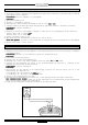
S’ils ne fonctionnent pas:
1)1)
1)1)
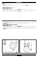
1) Tester
l’interrupteur des feuxl’interrupteur des feux
l’interrupteur des feuxl’interrupteur des feux
l’interrupteur des feux , démonter le protège-guidon, débrancher le connecteur du commutateur droit du
connecteur du câblage (4 voies), mettre l’interrupteur en position “ON”, vérifier avec un testeur (en position OHM)
la continuité entre les câbles
jaune/rougejaune/rouge
jaune/rougejaune/rouge
jaune/rouge et
bleu clairbleu clair
bleu clairbleu clair
bleu clair .
DiscontinuitéDiscontinuité
DiscontinuitéDiscontinuité
Discontinuité : remplacer le commutateur droit.
Continuité:Continuité:
Continuité:Continuité:
Continuité:
2)2)
2)2)
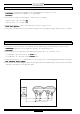
2) Contrôler la résistance de la bobine d’éclairage du volant magnétique (VM), (testeur en c.a.), débrancher le connecteur de
sortie du volant qui porte les câbles
jaunejaune
jaunejaune
jaune et
marronmarron
marronmarron
marron, brancher: borne (
++
++
+ ) du testeur au câble
jaunejaune
jaunejaune
jaune , borne (
--
--
-) du testeur à la
masse sur le châssis, mettre le moteur en route (7.000 tours/mn): la valeur de sortie ne doit pas être inférieure à 42V.
Valeur hors spécificationsValeur hors spécifications
Valeur hors spécificationsValeur hors spécifications
Valeur hors spécifications : remplacer le volant magnétique.
Valeur conforme aux spécificationsValeur conforme aux spécifications
Valeur conforme aux spécificationsValeur conforme aux spécifications
Valeur conforme aux spécifications : continuer la recherche.
3)3)
3)3)
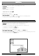
3) Contrôler le régulateur de tension (R), brancher le testeur (c.a.) au connecteur du régulateur (en le laissant inséré)
borne du testeur (
++
++
+ ) > au câble
jaune jaune
jaune jaune
jaune
borne du testeur (
--
--
-) > au câble
noirnoir
noirnoir
noir
mettre le moteur en route (7.000 tours/ms), vérifier si la tension de sortie est > 12V.
Valeur hors spécificationsValeur hors spécifications
Valeur hors spécificationsValeur hors spécifications
Valeur hors spécifications : remplacer le régulateur de tension.
Valeur conforme aux spécificationsValeur conforme aux spécifications
Valeur conforme aux spécificationsValeur conforme aux spécifications
Valeur conforme aux spécifications : continuer la recherche.
4)4)
4)4)
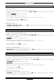
4) Contrôler le câblage, en vérifiant toutes les connexions des câblages d’éclairage et contrôler également, à l’aide
du schéma électrique, la correspondance des associations des couleurs de câbles.
S’assurer enfin qu’il n’y a pas de câbles interrompus ou de courts-circuits.
HEADLIGHT - TAILLIGHTS - DASHBOARD ILLUMINATIONHEADLIGHT - TAILLIGHTS - DASHBOARD ILLUMINATION
HEADLIGHT - TAILLIGHTS - DASHBOARD ILLUMINATIONHEADLIGHT - TAILLIGHTS - DASHBOARD ILLUMINATION
HEADLIGHT - TAILLIGHTS - DASHBOARD ILLUMINATION
If these do not work, proceed as follows:
1) Check
light switchlight switch
light switchlight switch
light switch by removing the upper handlebar cover and disconnecting the RH switch connector from the
4-way harness connector. Turn the switch to “ON” and check for continuity between the
yellow/red yellow/red
yellow/red yellow/red
yellow/red and
light bluelight blue
light bluelight blue
light blue
cables with a tester (set to OHM).
In case of
discontinuitydiscontinuity
discontinuitydiscontinuity
discontinuity , replace the RH switch.
In case of
continuitycontinuity
continuitycontinuity
continuity , carry on as follows:
2) Check the resistance of the magneto flywheel coil (VM) (tester set to AC) by uncoupling the flywheel output connector which
carries the
yellowyellow
yellowyellow
yellow and
brownbrown
brownbrown
brown cables and connecting the (
++
++
+ ) terminal of the tester to the
yellowyellow
yellowyellow
yellow cable and the (
--
--
-) terminal of
the tester to the frame to earth. Start up the engine and run at (7.000 rpm); output reading should not be less than 42V.
If a value other the above is read,If a value other the above is read,
If a value other the above is read,If a value other the above is read,
If a value other the above is read, replace the magneto flywheel
..
..
.
If value is as per above, If value is as per above,
If value is as per above, If value is as per above,
If value is as per above, continue with troubleshooting.
3) Check voltage regulator (R) by connecting the tester (set to AC) to the regulator connector (leaving the regulator
coupled), and
the (
++
++
+ ) terminal of the tester to the
yellow yellow
yellow yellow
yellow cable,
the (
--
--
-) terminal of the tester to the
black black
black black
black cable.
Start up the engine and run at (7.000 rpm); output reading should be more than 12V.
If a value other the above is read,If a value other the above is read,
If a value other the above is read,If a value other the above is read,
If a value other the above is read, replace the voltage regulator
..
..
.
If value is as per above, If value is as per above,
If value is as per above, If value is as per above,
If value is as per above, continue with troubleshooting.
4) Check the harness, making sure that all illumination harness connections are in order. Also check that cables are
properly connected by referring to the wiring diagram colour scheme.
Also check for broken cables and short circuits.
FAROS - LUCES TRASERAS - ALUMBRADO DEL TABLEROFAROS - LUCES TRASERAS - ALUMBRADO DEL TABLERO
FAROS - LUCES TRASERAS - ALUMBRADO DEL TABLEROFAROS - LUCES TRASERAS - ALUMBRADO DEL TABLERO
FAROS - LUCES TRASERAS - ALUMBRADO DEL TABLERO
Si no funcionan:
1) Ensayar el interruptor de las luces, desmontar el protector del manillar, desconectar el conectador del conmutador
derecho del conectador de cableado (4 vías), llevar el interruptor a la pos. “ON”, verificar por medio de un tester
(en pos. OHM) la continuidad entre los cables
amarillo/rojoamarillo/rojo
amarillo/rojoamarillo/rojo
amarillo/rojo y
azul claroazul claro
azul claroazul claro
azul claro .
Discontinuidad:Discontinuidad:
Discontinuidad:Discontinuidad:
Discontinuidad: substituir el conmutador derecho.
Continuidad:Continuidad:
Continuidad:Continuidad:
Continuidad:
2) Controlar la resistencia de la bobina de alumbrado del volante magnético (VM), (tester de c.a.), desconectar el
conectador de salida del volante que lleva los cables
amarillo amarillo
amarillo amarillo
amarillo y
marrónmarrón
marrónmarrón
marrón, conectar: borne (
++
++
+ ) del tester al cable
amarilloamarillo
amarilloamarillo
amarillo , borne (
--
--
-) del tester a la tierra en el chasis, poner en marcha el motor (7.000 revoluciones/minuto): el
valor no debe ser inferior a 42V.
Valor fuera de las especificaciones: Valor fuera de las especificaciones:
Valor fuera de las especificaciones: Valor fuera de las especificaciones:
Valor fuera de las especificaciones: substituir el volante magnético.
Valor conforme a las especificaciones: Valor conforme a las especificaciones:
Valor conforme a las especificaciones: Valor conforme a las especificaciones:
Valor conforme a las especificaciones: seguir buscando.
3) Controlar el regulador de tensión (R), conectar el tester (c.a.) al conectador del regulador (dejándolo puesto)
borne del tester (
++
++
+ ) > al cable
amarilloamarillo
amarilloamarillo
amarillo
borne del tester (
--
--
-) > al cable
negronegro
negronegro
negro
poner en marcha el motor (7.000 revoluciones/minuto), verificar si la tensión de salida es > 12V.
Valor fuera de las especificaciones: Valor fuera de las especificaciones:
Valor fuera de las especificaciones: Valor fuera de las especificaciones:
Valor fuera de las especificaciones: substituir el regulador de tensión.
Valor conforme con las especificaciones: Valor conforme con las especificaciones:
Valor conforme con las especificaciones: Valor conforme con las especificaciones:
Valor conforme con las especificaciones: seguir buscando.
4) Controlar el cableado verificando todas las conexiones de los cableados de alumbrado y controlar incluso, con el
auxilio del esquema eléctrico, la correspondencia de las asociaciones de los colores de cables. Cerciorarse que
no haya cables interrumpidos o cortacircuitos.