
Owner's manual


12 www.accel-ignition.com
ACCEL IS A DIVISION OF THE MR. GASKET PERFORMANCE GROUP
10601 MEMPHIS AVE. #12, CLEVELAND, OH 44144
216.688.8300 FAX 216.688.8306
FORM 1486AC
11/06
Made in U.S.A.
Printed in U.S.A.
connected to ground when the switch is active, and has a
maximum current rating of 10 amps. NOTE: The RPM range
for this switch is 1000 to 12, 8000 and the off RPM (mode
6) must be at least 100 RPM higher than the on RPM
(mode 5).
Mode B
– This is RPM Switch 1. It is selected when the
ORANGE wire coming out of the end panel is grounded.
The range is .1 to 15 degrees in .1 degree steps.
Mode C
– This is RPM Switch 2. It is selected when the
GREEN wire coming out of the end panel is grounded. The
range is .1 to 15 degrees in .1 degree steps.
Mode D
– Boost timing retard degrees per PSI of boost. If
you have an optional 2 BAR, #716 or 3 BAR, #717 MAP
sensor connected, the ACCEL 500+ will retard the timing as
the boost pressure increases. Mode D tells the system how
many degrees to retard the timing for each pound of boost.
The range is .1 to 4 degrees per pound of boost and
adjusts in .1 degree increments The MAP sensor plugs into
the optional harness #29785 which connects to the 3 wire
connector that comes out of the front panel. If you don’t
have a MAP sensor installed, this function has no effect.
Mode E
– Cylinder number select. Set this to however many
cylinders your engine has. The range is 4 to 12 cylinders,
even-fire ONLY!
Mode F
– MAP sensor select. There are two MAP sensors
available that are compatible with the ACCEL 500+. One is
a 2 Bar sensor (P/N 716), which is good for about 15 PSI of
boost, and the other is a 3 Bar sensor (P/N 717), good for
about 30 PSI of boost. You will also need to purchase MAP
Sensor Harness 29785. Use mode F to tell the ACCEL
500+ which sensor you are using. If you don’t have a MAP
sensor installed, this function has no effect.
Mode 2
– This is the auxiliary RPM limiter, and it is activated
when the RED wire coming out of the end panel is
grounded. The range is the same as the Mode 1 RPM
limiter. This RPML will over-ride the Mode 1 RPML when it
is active.
Mode 3
– This is the auxiliary RPM limiter, and it is activated
when the BLACK wire coming out of the end panel is
grounded. The range is the same as the Mode 1 RPM
limiter. This RPML will over-ride the Mode 1 and 2 RPM
limiters when it is active.
Retard Stages Modes 4, 5, 6 and 7- Utilize in Sequence.
Mode 4
– This is the first selectable high-speed timing
retard. It is selected when the ORANGE wire coming out of
the end panel is grounded. The range is .1 to 15 degrees in
.1 degree steps.
Mode 5
– This is the second selectable high-speed timing
retard. It is selected when the YELLOW wire coming out of
the end panel is grounded. The range is .1 to 15 degrees in
.1 degree steps.
Mode 6
– This is the third selectable high-speed timing
retard. It is selected when the PURPLE wire coming out of
the end panel is grounded. The range is .1 to 15 degrees in
.1 degree steps.
Mode 7
– This is the fourth selectable high-speed timing
retard. It is selected when the WHITE wire coming out of
the end panel is grounded. The range is .1 to 15 degrees in
.1 degree steps.
Mode 8
– Start retard value. This amount of retard is applied
whenever the engine RPM is below 500. The range is .1 to
10 degrees in .1 degree steps.
Modes 9 and A
– RPM Window Switch. These two control
the built-in RPM activated “window” switch. Mode 9 sets
the RPM where the switch activates, and mode A sets the
RPM where the switch de-activates. This is useful if, for
example, you want to have your nitrous system only work
within a certain RPM range. The output wire for the RPM
switch is the VIOLET wire coming out of the end panel. It is
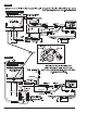
FIGURE 15