
Owner's manual


GENERAL INFORMATION
The ACCEL 500+ Ignition System Part Nos. 49500 are
not for marine use.
The RPM limiters in the ACCEL 500+ is not recommended
as an engine speed governor. The use of the RPM limiters
is not recommended for applications equipped with a
catalytic converter. Similarly, forcing engine RPM past the
RPM limiter continuously for long sustained intervals can
cause fuel build up in the exhaust system that may
adversely affect your application. The RPM limiting systems
will not work properly with odd-fire V6 applications.
Ignition Ballast Resistor / Loom Resistance Wire
The performance of the ACCEL 500+ is not affected by
the presence of the factory ignition resistors or ignition
ballast resistors in the wire from the ignition switch.
Standard Ignition Bypass (Bypass Connector)
The Bypass Connector (supplied) fits into the Ignition
Control Harness to convert back to standard ignition. If
you use the Bypass Connector, use ignition ballast
resistors designed for your vehicle’s distributor and coil
(see diagrams for more information). This bypass method
does not work with magnetic pickup distributor or crank
trigger ignition. Racing Applications: It is not necessary to
install ignition ballast resistors. However, do not use the
Bypass Connector until the ignition ballast resistors are
installed in the wire from the ignition switch.
Ignition Coils
The ACCEL 500+ Electronic Ignition Controls are designed
to work with most original equipment ignition coils. For
optimum performance use the ACCEL E Coil Part Number
140009 (Up to 7,500 RPM), Part No. 140019 (Up to 10,000
RPM), Mallory PROMASTER® Coil Part No. 29440 (up to
7,500 RPM) or Part No. 29625 (up to 10,000 RPM).
Fuel Injection
Some fuel injection systems need a voltage spike signal
from the ignition coil before they will operate properly.
This signal changes once ACCEL 500+ Electronic Ignition
Controls are installed. The Mallory Fuel Injection and
Tachometer Adapters Part Nos. 29074 and 29078 supply
the proper signal to the vehicle computer to operate the
fuel injection system. Installation procedure and diagrams
are supplied with these adapters.
Spark Plug Wires
YOU MUST USE suppression type (carbon core, spiral
core, suppression core) spark plug wire. We recommend
spiral core ignition wire, such as ACCEL 300+ Race Ignition
Wire. Suppression type spark plug wires prevent false
triggering and possible premature
ignition or accessory failures.
DO NOT USE solid core (copper
core; stainless steel core) spark plug wire with any electronic
ignition system or accessory
.
Spark Plug Gaps
For street applications, use your engine manufacturer’s
specifications. For racing applications, start with your
engine manufacturer’s specifications, then experiment
with, and closely monitor, various gaps to achieve
maximum performance.
Electric Welding
Unplug the Ignition Control Harness from the ACCEL 500+
Electronic Ignition Control and unplug any distributor
harnesses (if possible) before any welding is done on the
vehicle.
External RPM Limiters
Mallory Proportional RPM Limiter Part Nos. 641-4, 641-6,
641-8, 642, 643 and 644 WILL NOT function with the
ACCEL 500+ Electronic Ignition Controls.
MOUNTING PROCEDURE
Step 1
Disconnect the battery (–) cable to cut power to the system.
Computerized vehicles: Disconnect the battery (–) cable
and let the vehicle sit overnight before proceeding. This
allows the computer to calibrate for the new ignition.
Step 2
Select a convenient location to mount the ACCEL 500+
Electronic Ignition Control. Keep the unit away from hot
engine components or extreme heat such as the exhaust
system and manifolds. Also, keep it away from moving
devices, such as fans, belts and linkages. The location
must be dry. Excessive moisture will damage components
inside the unit. Chose a location that will allow easy
access to the control port for adjusting the various
functions of the ignition.
Step 3
Choose one mounting method listed below for mounting
the ACCEL 500+ Electronic Ignition Control (3a, 3b, or 3c).
(3a) Mounting to a flat surface
• Center punch the mounting pattern on the mounting
surface using the housing holes to mark locations for
drilling mounting holes. Drill holes using a 7/32” drill bit.
• Hold the ACCEL 500+ Electronic Ignition Control in
position over the mounting holes.
• From the backside of the mounting surface, insert the
10-32 screws with lock washers through the mounting
holes and attach with the 10-32 nuts supplied.
(3c) Mounting to a flat surface with shock mounts (available
separately, PN 29069)
• Center punch the mounting pattern on the mounting
surface using the housing holes to mark locations for
drilling mounting holes. Drill holes using a 7/32” drill bit.
• Install the shock mounts into the side flanges of the
ACCEL 500+ and tighten nuts. Hold the unit in position
where it will be mounted.
• From the backside of the mounting surface, insert the
10-32 nuts with lock washers onto the shock mount
studs. Tighten each nut until snug. When running shock
mounts, it is necessary to run a ground wire (10-14 gauge)
from the ignition housing to a chassis ground.
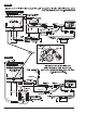
500+
FIGURE 1
2 www.accel-ignition.com ACCEL IGNITION