
Instruction Manual

Model HU-226
Technical Information
TI.226-05
HUMIDITY / TEMP SENSOR
Page 2 of 4
TYPICAL APPLICATIONS (wiring diagrams)
HU-226 humidity transducers are 4-20 mA output units powered with a
12-40 VDC supply.
The following describes the proper wiring of these humidity and temp sensors
with mA output:
HUMIDITY SENSOR:
1. Remove the terminal block by carefully pulling it off the circuit board.
2. Locate the [+] and [-] terminal markings on the board.
3. Attach the supply voltage to the [+] lead.
4. Connect the 4-20 mA output ([-] terminal) to the controller’s input terminal.
5. Ensure that the power supply common is attached to the common bus of
the controller.
6. Re-insert the terminal block to the circuit board and apply power to the unit.
7. Check for the appropriate output signal using a DVM set on DC milliamps
connected in series with the [-] terminal.
Input Signal
+
Common
+
+
Shield/Ground
Controller / Meter / Recorder
mA Output Transducer Only
12-40 VDC Power Supply
+
Controller / Meter / Recorder
mA Output Transducer Only
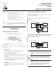
Figures 1 & 2 illustrate typical wiring diagrams for the HU-226, 4-20 mA,
two-wire humidity transducers.
Figure 1 - Wiring for mA Output Humidity Transducer with External DC
Power Supply
Figure 2 - Wiring for mA Output HumidityTransducer where Controller or
Meter has Internal DC Power Supply
RoHS
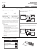
Mounting
HU-226 (DUCT) - Refer to Figure 6 for mounting dimensions.
1. Drill 5/8” hole in appropriate location.
2. Mount transducer on a vertical surface with two #8
self-tapping screws (not provided).
3. Pull wires through knockout and make necessary connec-
tions (see wiring diagrams).
4. Replace cover and tighten Philips screws.
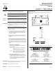
Wiring
Use maximum 12 AWG wire for wiring terminals. Refer to
Figures 1, 2, 3, & 4 for wiring information and Figure 5 for dip
switch designations.
Wiring HU-226 Units with mA Output
HU-226 Humidity Transducer with mA Output
Caution: If you are using grounded AC, the hot wire must be on
the [+] terminal. Also, if you are using a controller without built-in
isolation, use an isolation transformer to supply the HU-226
transducer.
Caution: This product contains a half-wave rectifier power
supply and must not be powered off transformers used to power
other devices utilizing non-isolated full-wave rectifier power
supplies.
Caution: When multiple units are powered from the same
transformer, damage will result unless all 24G power leads are
connected to the same power lead on all devices. It is manda-
tory that correct phasing be maintained when powering more
than one device from a single transformer.
mA Output
TEMP SENSOR:
1. Remove the terminal block by carefully pulling it off the circuit board.
2. Use shielded 18-22 AWG wire to connect temp sensor as shown in
Figures 1 & 2.
Humidity
Temp
Temp
Input
Humidity
Temp
Input Signal
+
Common
Shield/Ground
Temp
Input