
Instruction Manual

Model HU-226
Technical Information
TI.226-05
HUMIDITY / TEMP SENSOR
Page 3 of 4
RoHS
TYPICAL APPLICATIONS (wiring diagrams)
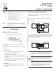
Neutral
Hot
+
Controller / Meter / Recorder
VDC Output Transducer Only 12-35 VAC Transformer
Figures 3 & 4 illustrate typical wiring diagrams for the HU-226, 0-5/0-10
VDC output humidity transducers.
Figure 3 - Wiring for VDC Output when applied with External AC Supply
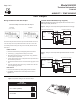
Figure 4 - Wiring for VDC Output when applied with External DC Power
Supply
Signal
+
Common
Supply
O
+
Controller / Meter / Recorder
VDC Output Transducer Only 12-40 VDC Power Supply
HU-226 humidity transducers with VDC output are field selectable 0-5 VDC or
0-10 VDC output and can be powered with either 12-40 VDC or 12-35 VAC.
The following describes the proper wiring of these humidity transducers with
VDC output:
Wiring HU-226 Units with VDC Output
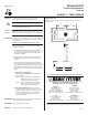
0 to 10 VDC
(Factory Default)
0 to 5 VDC
HU-226 Humidity Transducer with VDC Output
Figure 5 - Dip Switch Settings for HU-226 VDC Output
VDC Output
+ - 0
ON
1
2
Z S
temp
HUMIDITY SENSOR:
1. Remove the terminal block by carefully pulling it off the circuit board.
2. Locate the [+], [-] and [O] terminal markings on the board.
3. Attach the power wires to the [+] and [-] terminals. The [-] terminal is
also the negative output terminal.
4. Connect the [O] terminal, which is the positive VDC output terminal, to
the controller’s input terminal.
5. Re-insert the terminal block to the circuit board and apply power to the
unit.
6. Check the appropriate VDC output using a voltmeter set on DC volts
across the [O] and [-] terminals.
TEMP SENSOR:
1. Remove the terminal block by carefully pulling it off the circuit board.
2. Use shielded 18-22 AWG wire to connect temp sensor as shown in
Figures 3 & 4.
Input Signal
+
Common
Shield/Ground
Temp
Input
Input Signal
+
Common
Shield/Ground
Temp
Input
Humidity
Temp
Signal
+
Common
Supply
O
Humidity
Temp
HU-226
DUCT MOUNT
0 to 10 VDC (default)
0 to 5 VDC
1
2
O N
1
2
O N