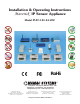
Installation & Operating Instructions Maverick IP Sensor Appliance Model IP-PC-101-44-VDC RoHS 8189 Century Blvd. • Minneapolis, MN 55317-8002 • USA 800-843-5116 • 952-556-4900 • Fax 952-556-4997 sales@mamacsys.com • www.mamacsys.com Baird House, Units 6&7 Pensnett Estate • Kingswinford West Midlands • DY6 7YA • United Kingdom 01384-271113 • Fax 01384-271114 4 Arminger Court, Unit 2 Holden Hill • S.A.
TABLE OF CONTENTS SECTION 1: Maverick Overview 1.0.0: Conformance and Testing Page 2 1.1.0: Specifications Page 3 1.2.0: Appliance Overview Page 4 1.3.0: Installation Page 5 1.4.0: Wiring Page 6 SECTION 2: Initial Configuration 2.0.0: Initial Configuration Page 7 2.1.0: Internet Protocol Page 8 2.2.0: Network & Email Configuration - Static IP Page 9 2.3.0: Network & Email Configuration - DHCP Page 9 2.4.0: Password/Clock Configuration Page 10 2.5.
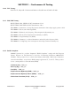
SECTION 1 - Conformance & Testing 1.0.0 FCC Testing - Rule Part 15, Subpart B - Unintentional Radiators Class B Limits 15.107 & 15.109. 1.0.1 EMC/EMI Testing - BS EN 55022:1998, CISPR 22:1997 Amendments 1 & 2. - BS EN 55024:1998 CISPR 24:1997 Amendments 1 & 2. - EN 61000-3-3: Limitations of voltage fluctuations and flicker in low-voltage supply systems <16A. - EN 61000-4-2: Electrostatic Discharge (ESD). - EN 61000-4-3: Radiated, radio frequency, Electromagnetic field immunity test.
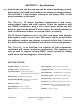
SECTION 1 - Specifications 1.1.0 Anyone who can surf the web now can do sensor monitoring, control, data logging, and email alerts without any training or custom software. All you need is a web browser running on any laptop, PDA, or cell phone anywhere in the world. The Maverick IP Sensor Appliance incorporates a web server, analog/digital inputs and relay outputs. Power the appliance with any 24VAC transformer, plug it into a hub/router, launch any web browser, punch in the default IP and connect.
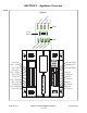
SECTION 1 - Appliance Overview 1.2.0 Po w e H r ea r Li t Be nk a t La n Figure 1 LEDs Reset Button DN IS-IPPC101.1 p O ut 2 ut pu O t3 ut pu t4 ut 24 VAC/VDC Neutral/Com Ground/Earth MAMAC SYSTEMS Out 1 NC Out 1 COM Out 1 NO Out 2 NC Out 2 COM Out 2 NO Out 3 NC Out 3 COM Out 3 NO Out 4 NC Out 4 COM Out 4 NO O O ut pu t1 LEDs ® Registered trademark MAMAC SYSTEMS, Inc.
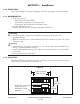
SECTION 1 - Installation 1.3.0 INSPECTION: Inspect the package for damage. If damaged, notify the appropriate carrier immediately. 1.3.1 REQUIREMENTS: • Tools (not provided) - Digital Volt-ohm Meter (DVM). - Appropriate screwdriver for mounting screws. - Appropriate drill and drill bit for mounting screws. • Four #6 sheet metal screws. • Training: Installer must be a qualified, experienced technician. Warning: • Disconnect power supply before installation to prevent electrical shock and equipment damage.
SECTION 1 - Wiring 1.4.0 Terminate the IP Sensor Appliance as shown in fig. 3. 1.4.1 Use a UL rated 24VAC class-2 transformer or a UL rated 24VDC power supply with transformer isolation. WARNING: Maximum supply voltage MUST NOT EXCEED 35VAC/35VDC. CAUTION: The appliance and all sensors connected must be wired with all neutral/common connections with the same polarity. All sensors and the appliance neutral/common must terminate at the transformer/power supply neutral/common.
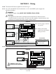
SECTION 2 - Initial Configuration 2.0.0 For first time start-up, a laptop/PC and a crossover cable is required. If a crossover cable is not available, a hub can also be used as shown in fig. 5B. Terminate the appliance as shown in fig. 3. Unplug the input and output terminal blocks and leave only the power terminal block plugged in. Attach the crossover cable to the appliance and the other end to the laptop ethernet jack as shown in fig. 5A.
SECTION 2 - Internet Protocol 2.1.0 Insure that the laptop/PC network settings are set up correctly. From the Start menu, go to Settings, click Network Connections. Double click the Local Area Connection icon. Local Area Connection Status screen will open. Click on the Properties tab. Local Area Connection properties page will open. Scroll down to Internet Protocol (TCP/IP) and click/highlight. Now click on the Properties tab on the same screen. Internet Protocol (TCP/IP) Properties page will open.
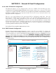
SECTION 2 - Network & Email Configuration 2.2.0 Static IP Network Configuration The Maverick appliance can be configured with a Static IP or DHCP. From the Main page select Configuration and highlight Network/Email and the appliance will serve up a new page. The default configuration is Static IP (DHCP disabled). Fill in the Device IP Address, Subnet Mask, Default Gateway and DNS Server in the appropriate fields. The static IP set up is exactly the same as any laptop/PC network configuration.
SECTION 2 - Password/Clock Configuration 2.4.0 When connecting to the IP Sensor Appliance the first time, the Password/Clock page will be served up by the Maverick to force the user to change the default password and username. Current time, date, firmware version and MAC address is displayed on the Password/Clock page for reference purposes. 2.4.1 Node I.D.: Please fill in the name of the appliance in this field. Maximum 20 alpha and/or numeric characters (upper or lower case). 2.4.
SECTION 2 - Sensor Inputs, Email Alert & Setpoint Control Configuration 2.5.0 From the navigation bar, click/highlight Configuration and pick Inputs. The appliance will serve up the input configuration page. Based on the sensors selected, click the appropriate radio button (0-5VDC, 0-10VDC or Digital). Next click Save. All inputs will be automatically configured to accept the specified sensor input. (Default is 0-10 VDC input).
SECTION 2 - Sensor Inputs, Email Alert & Setpoint Control Configuration 2.5.5 Email Alerts: If an email alert is desired on input # 1, please enable by clicking the radio button. Enter the desired lower and upper values for the alert and click on the down arrow to unable or disable the alert.
SECTION 2 - Output Configuration 2.6.0 To configure the outputs, click on the Configuration icon in the navigation bar and select Outputs. The four outputs can be controlled by the inputs or can be programmed to switch on and off based on a time schedule. Outputs can also have both sensor input based setpoint control AND time control concurrently.
SECTION 2 - Data Logging 2.7.0 The Maverick logs each sensor input data in a comma separated (CSV) file. Up to 2048 samples can be logged for each input. The logging interval can be from 1 second to 99.99.99 hours for each sample. The appliance can also attach the log to an email alert if configured. From the navigation bar, highlight Configuration and select Logging Setup and a new page will open up.
SECTION 3 - Network Configuration Options 3.0.0 Static IP Address: After the initial configuration, power down the appliance by unplugging the power terminal block and disconnect the crossover cable. CAUTION: Each time the static IP is changed, power cycle the appliance to load up the new static IP. Connect the Maverick to the ethernet as shown in fig. 7. Three options are available-- 1) Use a CAT 5 patchcord and plug it into a hub or switch and connect the hub/switch to a router on the web.
SECTION 3 - Network Configuration Options 3.0.1 DHCP IP Assignment: If during initial configuration DHCP was enabled, power down the appliance and disconnect the crossover cable. Connect the Maverick to the ethernet as shown in fig. 7. Three options are available-- 1) Use a CAT 5 patchcord and plug it into a hub or switch and connect the hub/switch to a router on the web. 2) Use a CAT 5 cable to connect directly to the router.
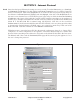
SECTION 3 - Main Page 3.1.0 After the initial configuration, any web browser running on a laptop/PC, PDA or a web enabled mobile/cell phone can connect to the appliance. The Maverick will serve up the Main page showing the status of all 4 inputs and outputs. The Main page also displays email alerts and the auto or manual status of the outputs. The appliance uses AJAX and XML to update the values of all fields on the Main page without refreshing the whole page. As a result one second updates are possible.
SECTION 3 - Manual Control 3.1.1 Manual Control: Any output can be controlled manually from the web browser by clicking on the Manual Control icon on the navigation bar. A new page will be served up showing the current output control status and state. Suppose the user desires to turn output #1 on manually. Click the Manual radio button for Output #1 and click Save. The status will change from Automatic to Manual. Now click the On radio button for Output #1 and hit Save.
SECTION 3 - Data Logging 3.1.2 Data Logging: The Maverick logs data in a CSV (Comma Separated Values) file which can be imported into NotePad, WordPad, Word or Excel. To view a CSV file of the logged data, navigate to the Data Logging icon on the navigation bar and highlight CSV. Click the desired Input and the appliance will serve up the data. To Save or to Import the CSV file, click File on the browser navigation bar and highlight Save As. Enter a file name and save the data on the laptop/PC or PDA.
SECTION 3 - Reset Button & XML 3.2.0 Reset Button: If the user misplaces the appliance IP address or forgets the password, the Reset is designed as a Back Door. If any of the above happens, press and hold the reset button for more than 20 seconds until the heartbeat light stops pulsing; release the switch. The Maverick IP Address, User Name, Password, Input, Output and Logging configuration will revert back to Factory Defaults. 3.3.0 XML: The appliance has XML embedded with formatted input and output data.