Installation & Operating Instructions Maverick IP Sub Metering Appliance Model IP-SM-101 RoHS 8189 Century Boulevard • Minneapolis, MN 55317-8002 • USA 800-843-5116 • 952-556-4900 • Fax 952-556-4997 sales@mamacsys.com • www.mamacsys.com Baird House, Units 6&7 Pensnett Estate • Kingswinford West Midlands • DY6 7YA • United Kingdom 01384-271113 • Fax 01384-271114 4 Arminger Court, Unit 2 Holden Hill • S.A.
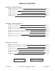
TABLE OF CONTENTS SECTION 1: Maverick Overview 1.0.0: Conformance and Testing Page 2 1.1.0: Specifications Page 3 1.2.0: Appliance Overview Page 4 1.3.0: Installation Page 5 1.4.0: Wiring Page 6 SECTION 2: Initial Configuration 2.0.0: Initial Configuration Page 7 2.1.0: Internet Protocol Page 8 2.2.0: Password/Clock Configuration Page 9 2.3.0: Network & Email Configuration - Static IP Page 10 2.4.0: Network & Email Configuration - DHCP Page 10 2.5.0: Meter Configuration Page 11 2.6.
SECTION 1 - Conformance & Testing 1.0.0 FCC Testing - Rule Part 15, Subpart B - Unintentional Radiators Class B Limits 15.107 & 15.109. 1.0.1 EMC/EMI Testing - BS EN 55022:1998, CISPR 22:1997 Amendments 1 & 2. - BS EN 55024:1998, CISPR 24:1997 Amendments 1 & 2. - EN 61000-3-3: Limitations of voltage fluctuations and flicker in low-voltage supply systems <16A. - EN 61000-4-2: Electrostatic Discharge (ESD). - EN 61000-4-3: Radiated, radio frequency, Electromagnetic field immunity test.
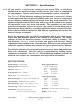
SECTION 1 - Specifications 1.1.0 All you need is a web browser running on any laptop, PDA, or cell phone anywhere in the world to monitor and log electric, gas, water or compressed air consumption. Receive email alerts if consumption crosses a threshold. The Maverick IP Sub Metering Appliance incorporates a web server, accepts a pulse input from any energy meter (KWH, water, gas, steam or compressed air) and displays consumption by the minute, hour, day, week and month.
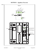
SECTION 1 - Appliance Overview 1.2.0 Po w e H r ea r Li tbea nk t LA N Figure 1 LEDs RESET Button Pulse 24 VAC/VDC Neutral/Com Ground/Earth MAMAC SYSTEMS LAN DN IS-IPSM101.1 ® Registered trademark MAMAC SYSTEMS, Inc. 4 of 17 Pulse Dry Contact Only 3.3 VDC <5.
SECTION 1 - Installation 1.3.0 INSPECTION: Inspect the package for damage. If damaged, notify the appropriate carrier immediately. 1.3.1 REQUIREMENTS: • Tools (not provided) - Digital Volt-ohm Meter (DVM). - Appropriate screwdriver for mounting screws. - Appropriate drill and drill bit for mounting screws. • Four #6 sheet metal screws. • Training: Installer must be a qualified, experienced technician. Warning: • Disconnect power supply before installation to prevent electrical shock and equipment damage.
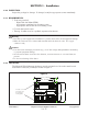
SECTION 1 - Wiring 1.4.0 Terminate the IP Sub Metering Appliance as shown in Figure 3. 1.4.1 Use a UL rated 24VAC Class-2 transformer or a UL rated 24VDC power supply with transformer isolation. WARNING: Maximum supply voltage MUST NOT EXCEED 35VAC/35VDC. 1.4.2 Figure 3 Note: Use 18-gauge conductor for ground. Note: Always disconnect power from unit before wiring a sensor. MAMAC SYSTEMS 24 VAC/VDC TRANSFORMER/ POWER SUPPLY 24 VDC/VAC Neutral/Common PULSE DRY CONTACT ONLY 3.3 VDC < 5.
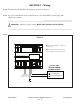
SECTION 2 - Initial Configuration 2.0.0 For first time start-up, a laptop/PC and a crossover cable is required. If a crossover cable is not available, a hub can also be used as shown in Figure 4B. Terminate the appliance as shown in Figure 3. Unplug the input and output terminal blocks and leave only the power terminal block plugged in. Attach the crossover cable to the appliance and the other end to the laptop ethernet jack as shown in Figure 4A.
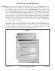
SECTION 2 - Internet Protocol 2.1.0 Insure that the laptop/PC network settings are set up correctly. From the Start menu, go to Settings, click Network Connections. Double-click the Local Area Connection icon. Local Area Connection Status screen will open. Click on the Properties tab. Local Area Connection Properties page will open. Scroll down to Internet Protocol (TCP/IP) and click/highlight. Now click on the Properties tab on the same screen. Internet Protocol (TCP/IP) Properties page will open.
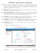
SECTION 2 - Password/Clock Configuration 2.2.0 When connecting to the IP Sub Metering Appliance the first time, the Password/Clock page will be served up by the Maverick to force the user to change the default password and username. Current time, date, firmware version and MAC address is displayed on the Password/Clock page for reference purposes. 2.2.1 Node I.D.: Please fill in the name of the appliance in this field. Maximum 20 alpha and/or numeric characters (uppercase or lowercase). 2.2.
SECTION 2 - Network & Email Configuration 2.3.0 Static IP Network Configuration The Maverick appliance can be configured with a Static IP or DHCP. From the Main page select Configuration and highlight Network/Email, and the appliance will serve up a new page. The default configuration is Static IP (DHCP disabled). Fill in the Device IP Address, Subnet Mask, Default Gateway and DNS Server in the appropriate fields. The Static IP set up is exactly the same as any laptop/PC network configuration.
SECTION 2 - Meter Configuration 2.5.0 Caution: Before starting the IP Sub Metering Appliance, please insure that the time and date are configured to maintain data integrity. 2.5.1 Note: Disconnect the pulse input terminal block. 2.5.2 Reset Meter: Click the Reset Meter button to reset all data fields to zero. 2.5.3 Constant: Input the meter constant. The meter constant is the value per pulse. For example, if each pulse is equal to 100 Watts and the unit of measure is KWH, the meter constant will be 0.
SECTION 2 - Email Alerts & Periodic Email Reports 2.6.0 From the navigation bar, click to highlight Configuration and select Email Alerts/Reports. The appliance will serve up a new page to configure minute, hourly, daily, weekly or monthly email alerts and periodic email reports. Click on the desired email alert/periodic report. A new page will open for the specific time period. If an email alert is desired, click on the Alert Enable radio button. Enter the value in the Alert Value field.
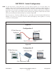
SECTION 3 - Network Configuration Options 3.0.0 Static IP Address: After the initial configuration, power down the appliance by unplugging the power terminal block and disconnect the crossover cable. CAUTION: Each time the static IP is changed, power cycle the appliance to load up the new static IP. Connect the Maverick to the ethernet as shown in Figure 6. Three options are available -- 1) Use a CAT 5 patchcord and plug it into a hub or switch and connect the hub/switch to a router on the web.
SECTION 3 - Network Configuration Options 3.0.1 DHCP IP Assignment: If during initial configuration DHCP was enabled, power down the appliance and disconnect the crossover cable. Connect the Maverick to the ethernet as shown in Figure 6. Three options are available -- 1) Use a CAT 5 patchcord and plug it into a hub or switch and connect the hub/switch to a router on the web. 2) Use a CAT 5 cable to connect directly to the router.
SECTION 3 - Main Page 3.1.0 After the initial configuration, any web browser running on a laptop/PC, PDA or a web-enabled mobile/cell phone can connect to the appliance. The Maverick will serve up the Main page displaying consumption by the Minute, Day, Week, Month and Year. For each time period, there is a countdown timer for the time remaining in the current period. The previous period value is also displayed. Alert Status for each period consumption is also shown.
SECTION 3 - Reset Button & XML 3.2.0 Reset Button: If the user misplaces the appliance IP address or forgets the password, the RESET is designed as a Back Door. If any of the above happens, press and hold the RESET button for more than 20 seconds until the Heartbeat LED stops pulsing; release the switch. The Maverick IP Address, Username, and Password configuration will revert back to factory defaults. 3.3.0 XML: The appliance has XML embedded with formatted input and output data.
Figure 7 -