
Manual
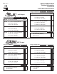

Accuracy*: ±1% FS
Overpressure: 10 PSID
Supply Voltage: 12-40 VDC
12-35 VAC (VDC output units only)
Supply Current: VDC Units - 10 mA max.
mA Units - 20 mA max.
Enclosure: 18 Ga C. R. Steel NEMA 4 (IP-65) or Panel Mount Chassis
Finish: Baked on enamel-PMS2GR88B
EMC Conformance: EN 55022, 55024, 61000-3-3,
61000-4-2, 3, 4, 5, 6 & 11
Compensated Temp Range: 25°F-150°F (-4°C-65°C)
T. C. Error: ±0.0125%/°F (.02%/°C)
Operating Temp Range: 0°F-175°F (-18°C-80°C)
Media Compatibility: Clean dry air or any inert gas
Environmental: 10-90%RH Non-Condensing
Termination: Unpluggable screw terminal block
Wire Size: 12 Ga max.
Load Impedance: 1.6K ohms max. at 40 VDC (mA output units)
1K ohms min. (VDC output units)
Weight: Enclosure - 1.0 lbs. (.45 kg)
Panel Mount - 0.5 lbs. (.25 kg)
PACKAGING RANGE OUTPUT
SPECIFICATIONS
Inspection - Inspect the package for damage. If damaged, notify the
appropriate carrier immediately. If undamaged, open the package and
inspect the device for obvious damage. Return damaged products.
Requirements
Mounting
274 (enclosure)
275 (panel mount)
R1
("wc)
R2
("wc)
R3
("wc)
R4
("wc)
R5
(pa)
R6
(pa)
R7
(pa)
R8
(pa)
0 TO 0.10 / -0.05 TO +0.05
0 TO 1.0 / 0 TO 0.5 / 0 TO 0.25 /
-0.5 TO +0.5 / -0.25 TO +0.25 /
-0.125 TO +0.125
0 TO 5.0 / 0 TO 2.5 / 0 TO 1.25 /
-2.5 TO +2.5 / -1.25 TO +1.25 /
-0.625 TO +0.625
0 TO 30 / 0 TO 15 / 0 TO 7.5 /
-15.0 TO +15.0 / -7.5 TO +7.5 /
-3.75 TO + 3.75
0 TO 25 / -12.5 TO +12.5
0 TO 250 / 0 TO 125 / 0 TO 62.5 /
-125 TO +125 / -62.5 TO +62.5 /
-31.25 TO +31.25
0 TO 1250 / 0 TO 625 / 0 TO 312.5 /
-625 TO +625 / -312.5 TO +312.5 /
-156.25 TO +156.25
0 TO 7500 / 0 TO 3750 / 0 TO 1875 /
-3750 TO +3750 / -1875 TO +1875 /
-937.5 TO +937.5
(4-20 mA
2-wire)
(0-5 VDC or
0-10 VDC field
selectable)
mA
VDC
For Additional Information See PR-274/275 Data Sheet
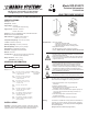
INSTALLATION
Model PR-274/275
Technical Information
TI.274/275-06
LOW PRESSURE SENSOR
Warning:
• Disconnect power supply before installation to prevent electrical
shock and equipment damage.
• Make all connections in accordance with the job wiring diagram
and in accordance with national and local electrical codes. Use
copper conductors only.
Caution:
• Use electrostatic discharge precautions (e.g., use of wrist straps)
during installation and wiring to prevent equipment damage.
• Avoid locations where severe shock or vibration, excessive
moisture or corrosive fumes are present. NEMA Type 4 housings
are intended for outdoor use primarily to provide a degree of
protection against wind-blown dust, rain, and hose-directed water.
• Do not exceed ratings of the device.
The PR-274/275 must be mounted as indicated by the arrows on
the enclosure. Refer to Figure 7 for mounting dimensions.
1. Remove the transducer cover using a Phillips head
screwdriver.
2. Select the mounting location.
3. Mount transducer on a vertical surface with two #8
self-tapping screws (not provided).
4. Transducer must be mounted above the pressure pick-up or a
J-Loop must be incorporated in the tubing to function as a
condensate trap.
5. Pull wires through bottom of enclosure and make
necessary connections.
6. Replace cover and make pneumatic connections.
• Tools (not provided)
- Digital Volt-ohm Meter (DVM)
- Appropriate screwdriver for mounting screws
- Appropriate drill and drill bit for mounting screws
• Appropriate accessories
• Two #8 self-tapping mounting screws (not provided)
• Training: Installer must be a qualified, experienced technician
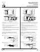
Wiring
Use maximum 12 AWG wire for wiring terminals. Use flexible 1/4"
O.D. 5/32" I.D. tubing for the high and low pressure connections.
Refer to Figures 1, 2, 3, & 4 for wiring information and Figures 5 &
6 for switch designations.
(Wiring Instructions continued on pages 2 and 3.)
8189 Century Boulevard • Minneapolis, MN 55317-8002 • USA
800-843-5116 • 952-556-4900 • Fax 952-556-4997
sales@mamacsys.com • www.mamacsys.com
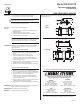
ORDERING INFORMATION
RoHS
Enclosure Mount
Transducer
Panel Mount
Transducer
Caution:
• Condensate or moisture must not enter pressure sensor ports