Vertical Water-to-Water Heat Pumps With R-410A Installation, Operation and Maintenance Manual Sizes: 064 to 480 Model: K Vintage MAMM-WSHP-IOM-1KA (September 2011) P/N 71144912
Table of Contents Model Nomenclature ················································································································3 Transportation and Storage ····································································································3 Installation ································································································································4 Unit Location ···········································································
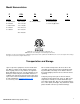
Model Nomenclature F W- H- K BTU/hr Cooling Unit Type Temperature Range Vintage F = 208-230/60/3 064 = 58,437 W = Water-to-Water G = 460/60/3 120 = 127,792 J = 380-415/50/3 170 = 172,906 K = 575/60/3 270 = 257,319 S = 380/60/3 360 = 350,047 Voltage -170- H = Standard Range L = Low Temp Operation 480 = 459,580 “Mammoth” is a registered trademark of Mammoth, Inc. ©Mammoth, Inc. 2011. All rights reserved throughout the world.
Installation General IMPORTANT: Mammoth water source heat pumps should be installed only by qualified personnel, experienced in the installation of this equipment and related systems. Read these instructions carefully before unpacking, installing and operating this unit. 1. To prevent damage, this equipment should not be operated during the construction period. 2. Inspect the unit for any specific tagging numbers indicated by the factory per a request from the installing contractor. 3.
Unit Location Locate the unit in an area that allows for easy removal of the compressor and control box access panels. The diagram below shows minimum suggested clearances. Any additional clearances would be beneficial, but not always necessary. The electrical connections are accessible from the front. The compressor can be accessed from either side. There are no air filter, ductwork or ventilation air requirements for K-Vintage water-to-water units.
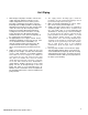
Unit Piping 1. All K-Vintage heat pumps should be connected to supply and return piping in a two-pipe reverse return configuration. A reverse return system is inherently self-balancing and requires only trim balancing where multiple quantities of heat pumps with different flow and pressure drop characteristics exist in the same loop. Check for proper water balance by measuring differential temperature reading across the water connections.
Cleaning and Flushing IMPORTANT: Prior to first operation of K-Vintage units, the water circulation system must be cleaned and flushed of all construction dirt and debris. After the cleaning and flushing has taken place, the initial connection should have all valves wide open in preparation for the water system flushing. 1. If the K-Vintage units are equipped with optional water shutoff valves, either electric or pressure operated, the supply and return run-outs must be connected at each heat pump location.
Start-up Before powering up any K-Vintage unit, check the following: 1. The high voltage supply matches the nameplate. 2. Field wire size, breakers and fuses are the correct size. 3. Water piping is complete and correct. 4. The closed loop system is flushed and purged. 5. Loop pumps are correctly wired. 6. Access panels on the unit are in place and secured. 7. Temperature controller is in the “Off” position. IMPORTANT NOTE: Avoid starting any electrical equipment for the first time alone.
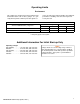
Operating Limits Environment This equipment is designed for indoor installation only. Sheltered locations such as attics, garages, etc., generally will not provide sufficient protection against ex- tremes in temperature and/or humidity, and equipment performance, reliability, and service life may be adversely affected.
MAMMOTH CONTROLS HP 5 Microprocessor Control Board The standard HP 5 microprocessor control board provides complete control of a compressor, reversing valve and offers numerous safety features and troubleshooting fault indicators. The HP 5 unit is designed to operate with Mammoth’s existing series of wall thermostats and arrives factory-installed and wired. Operation and maintenance (OM) instructions for the HP 5 control board are contained in a separate document (MAMM-WSHP-IOM-1HP5).
I/O 560 Controller Mammoth I/O Zone 560 controller delivers powerful control and communications features all in a compact, economical package. Fully capable of operating in a 100% stand-alone control mode, the I/O Zone 560 can connect to a Building Automation System (BAS) using any of today’s most popular protocols, such as BACnet, Modbus, N2, LonTalk. The I/O Zone 560 also supports communication to the Mammoth line of intelligent space sensors and keypad/display units.
I/O 583 Controller Mammoth I/O Zone 583 controller delivers powerful control and communications features all in a compact, economical package. Fully capable of operating in a 100% stand-alone control mode, the I/O Zone 583 can connect to a Building Automation System (BAS) using any of today’s most popular protocols, such as BACnet, Modbus, N2, and LonTalk,. The I/O Zone 583 also supports communication to Mammoth’s line of intelligent space sensors and keypad/display units.
I/O 560 & 583—Example of I/Os INPUTS Point Description UI #1 Thermistor/ Load Supply Water Temperature (Outlet) UI #2 Dry Contact Load Return Water Temperature (Inlet) UI #3 Source Leaving Water Temperature (Outlet) UI #4 Thermistor/ Source Entering Water Temperature (Inlet) UI #5 Dry Contact Compr Lockout (Waterflow) Compr #1 HP4 Alarm Compr #2 HP4 Alarm UI #6 Emergency Shut Down Remote Start (External Clock) Htg/Clg Changeover **** OUTPUTS Description Point DO #1 Pump Start* DO #2 Compressor Call #1 Dry C
General Maintenance Proper maintenance is important to provide the most efficient operation and longest life for your equipment. The following points are to serve as a general guide. Always consult with your maintenance contractor with regard to the specific requirements of your own installation. DANGER! Electric shock hazard. Turn of all power before servicing. Failure to do so may result in severe personal injury or death. The following should be checked only by a competent contractor.
Troubleshooting R-410A The In’s and Out’s of R-410A R-410A is a non-ozone depleting blend of two Refrigerants — HFC-125 and HFC-32 in a fifty percent mixture. Refrigerant 410A exhibits higher operating pressure and refrigeration capacity than R-22. Although R-410A is non-flammable at ambient temperature and atmosphere pressure, it can become combustible under pressure when mixed with air. (NOTE: R-410A should not be mixed with air under pressure for leak testing.
Performance Troubleshooting Performance Troubleshooting Unit doesn’t operate in cooling Heating Possible Cause Solution X X Low refrigerant charge Check superheat and subcooling X X Restricted metering device Check superheat and subcooling– replace X Defective reversing valve Perform RV touch test X X Unit undersized Recheck loads & sizing.
UNIT CHECK-OUT SHEET Customer Data Customer Name ________________________________________ Date _________________________________________ Address ________________________________________________________________________________________________ Phone ________________________________________________ Unit Number___________________________________ Unit Nameplate Data Make _______________________ Model Number ________________________ Serial Number _______________________ Compressor(s): # 1: RLA_______ LRA _______
Notes MAMM-WSHP-IOM-1KA (September 2011) 18
Notes MAMM-WSHP-IOM-1KA (September 2011) 19
info@mammoth-inc.com www.mammoth-inc.com Mammoth, Inc. has a policy of continuous product improvement and reserves the right to change design and specifications without notice. © 2011 Mammoth, Inc.