Multiple Circuit Horizontal and Vertical Water Source Heat Pumps With R-410A Installation, Operation and Maintenance Manual Sizes: 084 to 144 — Horizontal 084 to 288 — Vertical Model: M Vintage MAMM-WSHP-IOM-1MA (November 2011) P/N 71144916
Table of Contents Model Nomenclature ················································································································3 Transportation and Storage ····································································································3 Installation ································································································································4 Unit Location ···········································································
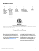
Model Nomenclature F V- H- M BTU/hr Cooling Unit Type Temperature Range Vintage F = 208-230/60/3 084 = 84,000 V = Vertical H = Standard Range G = 460/60/3 096 = 96,000 H= Horizontal J = 380-415/50/3 120 = 120,000 K = 575/60/3 144 = 144,000 Voltage -084- L = Low Temp Operation 168 = 168,000 192= 192,000 240 = 240,000 288 = 288,000 “Mammoth” is a registered trademark of Mammoth, Inc. ©Mammoth, Inc. 2011. All rights reserved throughout the world.
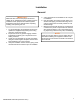
Installation General IMPORTANT: Mammoth water source heat pumps should be installed only by qualified personnel, experienced in the installation of this equipment and related systems. Read these instructions carefully before unpacking, installing and operating this unit 1. To prevent damage, this equipment should not be operated for supplementary heating and cooling during the construction period. 2.
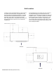
Unit Location Locate the unit in an area that allows for easy removal of the filter and access panels. The diagrams to the right show minimum suggested clearances. Any additional clearances would be beneficial, but not always necessary. Units need to be accessed from three sides: two panels for the two panels for the blower, two electrical access doors and one for the compressor compartment.
Ductwork and Attenuation Discharge ductwork is normally used with the Mvintage horizontal and vertical multiple circuit units. Return air ductwork may also be required. All ductwork should conform to industry standards of good practice as described in the ASHRAE Systems Guide.
Supply Piping 1. All heat pumps should be connected to supply and return piping in a two-pipe reverse return configuration. A reverse return system is inherently self-balancing and requires only trim balancing where multiple quantities of heat pumps with different flow and pressure drop characteristics exist in the same loop. Check for proper water balance by measuring differential temperature reading across the water connections.
Cleaning and Flushing 1. Prior to first operation of the M-Vintage horizontal and vertical units, the water circulation system must be cleaned and flushed of all construction dirt and debris 2. If the M-Vintage horizontal and vertical units are equipped with water shutoff valves, either electric or pressure operated, the supply and return runouts must be connected at each heat pump location. This will prevent the introduction of dirt into the heat pump. 3.
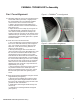
FANWALL TECHNOLOGY® Assembly Fan / Cone Alignment Figure 1—FANWALL® cone alignment 1. Temporarily attach the cone to the cell inlet using the screws and washers provided, or slightly loosen the screws holding the cone if already installed. Use a minimum of four screws for this step. a. Refer to the fan wheel overlap drawings provided to determine where to set the wheel with respect to the cone. b.
Start-up 1. Open all valves to full open position and turn on power to the heat pump. 2. Set room temperature sensor for “Fan Only” operation by selecting “Off” at the system switch and “On” at the fan switch. If “Auto” fan operation is selected, the fan will cycle with the compressor. Check for proper air delivery. 3. M-Vintage horizontal and vertical units have time delays which help protect the compressor(s) against short cycling.
Operating Limits Environment This equipment is designed for indoor installation only. Sheltered locations such as attics, garages, etc., generally will not provide sufficient protection against ex- tremes in temperature and/or humidity, and equipment performance, reliability, and service life may be adversely affected.
MAMMOTH DDC CONTROLS I/O Flex 6126 The standard factory-integrated DDC controller provides control flexibility that can be easily customized to meet any sequence of operation needs. It is fully capable of operating in a 100% stand-alone mode or can connect to a Building Automation System (BAS) using any of today’s four leading protocols: BACnet, Modbus, N2, and Lontalk. The base controller provides ample input/output capacity, plus support for an expander board if additional I/O capacity is required.
Examples of I/O’s INPUTS Point UD #1 Description +Pulse BMS Supply Air, Duct Static Reset or Room Air Temperature Setpoint Room Air Temperature UD #2 UD #3 RTD/Therm/Dry System Switch UD #4 Contact, 0-10VDC, High Static Low Static VFD in Bypass 0-20MA Economizer Lockout Cooling Lockout Heating Lockout UD #6 Supply Fan Status Compressor Fault Condensate Overflow UD #7 Duct Static Pressure or Airflow Switch UD #8 Filter Static Pressure or Dirty Filter Switch #1 UD #9 Outside Air Temper
MAMMOTH DDC CONTROLS Keypad Locally access controllers and operational properties with the easy-to-use BACview6 keypad/display. It plugs into an Rnet connection on a 6126 controller and allows you to display and modify properties. The BACview6 features a numeric keypad, directional keys, and four programmable function keys. A large 4-line by 40character backlit LCD display is provided for easy reading even in poor lighting conditions. The device also includes an alarm indicator light.
General Maintenance Normal maintenance on M-Vintage horizontal and vertical units is generally limited to filter changes. Air filter changes are required at regular intervals. The time period between changes will depend upon the project requirements. Some applications such as motels produce a lot of lint from carpeting and linen changes, and will require more frequent filter changes. It is suggested that the filter be checked at 60-day intervals for the first year until experience is acquired.
VFD GENERAL PURPOSE APPLICATION PARAMETERS Parameter Default Value b1-01 1 Description Reference Source Speed Control Method Run Source / b1-02 Comments 0 = Digital Operator (Adjust Motor Speed from keypad) 1 = Terminals (Speed Pot.
Troubleshooting R-410A Charging Due to the zeotropic nature of R-410A, it should be charged as a liquid. In situations where vapor is normally charged into a system, a valve should be installed in the charging line to flash the liquid to vapor while charging. The In’s and Out’s of R-410A R-410A is a non-ozone depleting blend of two Refrigerants — HFC-125 and HFC-32 in a fifty percent mixture. Refrigerant 410A exhibits higher operating pressure and refrigeration capacity than R-22.
Performance Troubleshooting Performance Troubleshooting Heating Cooling Possible Cause Solution Insufficient Capacity X X Dirty Filter Replace or clean Not cooling or heating properly X X Reduced or no air flow Check for dirty air filter and clean or replace, Check fan motor operation and airflow restriction. External static too high? Check static vs.
UNIT CHECK-OUT SHEET Customer Data Customer Name ________________________________________ Date _________________________________________ Address ________________________________________________________________________________________________ Phone ________________________________________________ Unit Number___________________________________ Unit Nameplate Data Make _______________________ Model Number ________________________ Serial Number _______________________ Compressor(s): # 1: RLA_______ LRA _______
info@mammoth-inc.com www.mammoth-inc.com Mammoth, Inc. has a policy of continuous product improvement and reserves the right to change design and specifications without notice. FANWALL TECHNOLOGY® and FANWALL® are trademarks of Huntair, Inc. This product is covered by one or more of the following U.S. patents (7,137,775; 7,179,046; 7,527,468; 7,597,534) and other pending U.S. or Canadian patent applications and/or foreign patents. © 2011 Mammoth, Inc.