
Manual

9
MAMM-WSHP-IOM-1MA (November 2011)
Fan / Cone Alignment
1. Temporarily attach the cone to the cell inlet using the
screws and washers provided, or slightly loosen
the screws holding the cone if already installed.
Use a minimum of four screws for this step.
a. Refer to the fan wheel overlap drawings pro-
vided to determine where to set the wheel with re-
spect to the cone.
b. Adjust the amount of overlap by moving the mo-
tor pedestal forward or backward to line up the
cone with the wheel (wheel/cone overlap is de-
signed to insert the cone 50% of the distance of the
rolled shroud lip on the wheel). Once you have the
wheel approximately located, tighten the ½” pedes-
tal bolts to 90ftlbs.
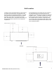
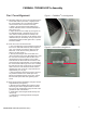
2. Center the cone in the wheel shroud.
a. The cone alignment can be a tedious process as
there are no tools that effectively work to align the
cone. It is a hands on process to align the cone.
Mammoth cones have a running clearance of
about 1/16" (see Figure 1).
b. Start by loosening the four screws that were
used to hold the cone for the depth alignment. Hold
the cone with one hand and with the other use a
drill to attach a screw to hold the cone in place.
Feel between the wheel inlet shroud and the cone
and set the gap to approximately 1/16" and tighten
the screw in that location (top of the cone is usually
the best place to start). At this point you should be
able to move the cone about that screw location,
adjusting the cone on the left or right until there is
approximately a 1/16" gap.
c. Spin the wheel by hand at this point to check for
any clearance issues. If the wheel spins clear,
tighten the remaining screws on the cone. Check
that the wheel spins clear after tightening each
screw.
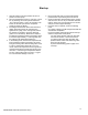
3. Attach the inlet airflow straightener using the formed
angle brackets (see Figure 2).
a. Start by loosely installing (don’t tighten screws
all the way) the bottom angle bracket. Set the air-
flow grid on the angle bracket. Align the side of the
grid with the end of the bracket.
b. Install either vertical angle bracket loosely and
check fit up.
c. Install the two remaining brackets and tighten
(see Figure 2).
FANWALL TECHNOLOGY
®
Assembly
Figure 1—FANWALL
®
cone alignment
Figure 2—Inlet airflow straightener
TYPICAL FAN-CONE
CLEARANCE
AIRSTRAIGHTENER
FIGURE 2
AIR STRAIGHTENER
ANGLE BRACKERS
FIGURE 1