V-Cube Slim™ Floor-by-Floor Cooling Systems Installation, Operation & Maintenance Manual Sizes: 180 to 350 Model: F-Series MAMM-VCS-IOM-4FA (October 2013) PN 71144925
Contents Nomenclature........................................................................................................................3 Introduction............................................................................................................................3 Warnings, Cautions and Notices...........................................................................................4 Receiving Inspection and Storage............................................................................
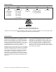
Nomenclature F 830 S H F Voltage Size (BTUH Cooling) Unit Type Temperature Range Design Series F = 208-230/3/60 180 = 180,000 V = Vertical H = Standard Range G = 460/3/60 240 = 240,000 J = 380/3/50 280 = 280,000 K = 575/3/60 310 = 310,000 L = Low Temperature 350 = 350,000 “Mammoth” is a registered trademark of Mammoth, Inc. ©Mammoth, Inc. All rights reserved throughout the world. Illustrations cover the general appearance of Mammoth products at the time of publication. Mammoth, Inc.
Warnings, Cautions and Notices Warnings, cautions and notices appear at appropriate locations throughout this manual. Your personal safety and the proper operation of this machine depend upon the strict observance of these precautions. Read this manual thoroughly before operating or servicing this unit. WARNING! Indicates a potentially hazardous situation which, if not avoided, could result in death or serious injury.
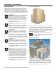
Disassembly and Assembly General Guidelines Figure 1: Unit As Shipped The Mammoth V Cube Slim Split is engineered to be disassembled in the field and moved through 36” doors into position then reassembled without breaking into the refrigeration circuits. Only qualified personel experienced in operation and maintenance of HVAC equipment should perform these procedures. WARNING! This equipment presents hazards of electricity, rotating parts, sharp edges, heat and weight.
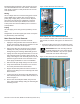
Mechanical lifting equipment is also required to remove the sub assemblies from the main chassis. Subassemblies weigh a minimum of 205 pounds and as much as 1500 pounds each. Figure 3: Main Electrical Panel Removal Wiring All low voltage wires are connected using quick-connect plugs. NEMA does not allow quick-connect plugs for power (high voltage) wiring. For this reason, all power wires have raw ends and are ‘hardwired’ to terminal blocks in the unit and require handtools for removal.
2. If still in place, remove the coil cabinet inner access panel from the side of the cabinet. IMPORTANT! The gasket between the FANWALL section and the main chassis must be replaced before reassembling the section. Failure to do so may cause air leakage and poor unit performance. 3. Remove the six fasteners (three on each side) connecting the sides of the coil cabinet to the main chassis. 4.
Installation WARNING! The installer must determine and follow all applicable codes and regulations. This equipment presents hazards of electricity, rotating parts, sharp edges, heat and weight. Failure to read and follow these instructions can result in property damage, severe personal injury or death. This equipment must be installed by experienced, trained personnel only. Mammoth recommends the unit be covered during construction to protect components from dust and other harmful material.
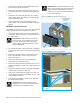
Figure 8: Clearances - Units Without Waterside Economizer SHELL AND TUBE SERVICE CLEARANCE ONLY FILTER REMOVAL ACCESS 42.0 [1067] 36.0 [914] 36.0 [914] SERVICE CLEARANCE SERVICE CLEARANCE Ductwork and Attenuation Discharge ductwork is normally used with the V-Cube Slim™. Return air ductwork may also be required. All ductwork should conform to industry standards of good practice as described in the ASHRAE Systems Guide.
Cleaning and Flushing Before building water is connected to the unit, the building water system must be flushed clean of particulate contaminants. Follow the procedures described in this section. IMPORTANT! Performance of WSHP units relies upon a building water supply filtered of any particulate and chemical contaminants. Before building water is connected to the unit, the building water system must be flushed clean of particulate contaminants.
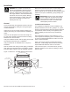
Figure 9: Electrical Connection Points Field control wiring Operating Voltage Incoming power supply must comply with the data in Table 1. Unit operation outside of the Min/Max range is not recommended and will result in premature component failure. Table 1: Operating voltages Power wiring .
Electrical Refrigerant Piping Electrical Terminals Mammoth V-Cube Slim units with DX cooling are shipped fully charged with refrigerant from the factory. No piping connections are needed and no field charging is required prior to operation of the system. Check the following prior to startup: Tighten all electrical terminals per the torque value listed on the connector. Electrical terminals are located within the main unit control panel.
monitor is set correctly as indicated on the electrical wiring diagram provided with your unit. 1. Install refrigeration gauges on the compressor circuit to be started. Blowers and Fans 2. Turn the unit system switch to the on position. Switch the motor protectors for the supply air fans to the On position (see page 6 for motor protector locations). Turn the system switch to the On position, then carry out the following checks: 3.
Chilled Water, Hot Water and Steam Coils Startup Visually check the coils and system piping for proper installation and any signs of leakage. Repair as needed. Check motorized valves and linkages for the following points of operation. Controls Startup For controls startup procedures, see the EPIC® Sequence of Controls documentation that is included in the packet of information that is zip-tied to the inside of the main control panel.
Troubleshooting Charts in this section provide general guidelines on troubleshooting problems with your V-Cube Slim unit. If Service assistance is required contact Mammoth Service at (952) 358-6618. For additional help diagnosing prob- lems or servicing the unit, contact your local Mammoth representative. For assistance locating your Mammoth representative, call 952-358-6600 or e-mail info@mammoth-inc.com.
Electrical Terminal Tightening Torques The following tables provide tightening torques, as recommended by the component manufacturer, for many of the electrical components provided on Mammoth units. If a torque value is provided on the component, use that value instead. Where no torque value is given or provided here, use the torques provided in the tables at the end of this section, which are taken from UL Standard 486A.
Table 5: Square D Molded Case Circuit Breakers – Mechanical lug kit wire ranges and torques Lug Mounting Screw Torque Wires Per Lug and Wire Ranges Wire Binding Screw Torque Lug Kit Lugs Per Kit Circuit Breaker Wires Domestic Metric Lb-in. N•m Wire* Lb-in. N•m AL50FA 3 FA, FH, FI 1 #14–#4 Cu or #12–#4 Al 2.5–25 mm2 4–25 mm2 40 4.5 Cu #14–#4 STR/ SOL Al #12–#4 STR Al #12–#10 SOL 35 35 15 4.0 4.0 1.7 AL100FA4 3 FC 1 #14–#3 Cu or #12–#1 Al 65 7.
Conductor size installed in connector Slotted head No. 10 or larger* Hexagonal head - external drive socket wrench AWG or kcmil (mm2) Slot width to 3/64 inch (1.2 mm) or slot length to 1/4 inch Slot width – over 3/4 inch (1.2 mm) or slot length over 1/4 inch Split-bolt connectors Other connectors 30 – 10 (0.05 – 5.3) 20 (2.3) 35 (4.0) 80 (9.0) 75 (8.5) 8 -8.4 25 (2.8) 40 (4.5) 80 (9.0) 75 (8.5) 6–4 (13.3 – 21.2) 35 (4.0) 45 (5.1) 165 (18.6) 110 (12.4) 3 -26.7 35 (4.0) 50 (5.
Unit CheckoutV-Cube Sheet Slim Unit Checkout Sheet Customer Data Customer Name ________________________________________ Date _________________________________________ Address ________________________________________________________________________________________________ Phone ________________________________________________ Unit Number___________________________________ Unit Nameplate Data Make _______________________ Model Number ________________________ Serial Number _______________________ Compressor
info@mammoth-inc.com www.mammoth-inc.com Mammoth, Inc. has a policy of continuous improvement and reserves the right to change design and specifications without notice. © 2013 Mammoth, Inc.