TELEDYNE HASTINGS INSTRUMENTS INSTRUCTION MANUAL 201/203 SERIES FLOW METERS/CONTROLLERS
Manual Print History The print history shown below lists the printing dates of all revisions and addenda created for this manual. The revision level letter increases alphabetically as the manual undergoes subsequent updates. Addenda, which are released between revisions, contain important change information that the user should incorporate immediately into the manual. Addenda are numbered sequentially.
Table of Contents 1. GENERAL INFORMATION............................................................................................................................................ 4 1.1. 1.2. 1.3. 1.4. 2. INSTALLATION AND OPERATION ............................................................................................................................. 7 2.1. 2.2. 2.3. 2.4. 2.5. 2.6. 2.7. 3. OVERALL FUNCTIONAL DESCRIPTION: ............................................................................
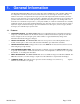
1. General Information The Hastings HFM-201/HFC-203 series Mass flow meter (HFM-201) and controller (HFC-203) are designed to accurately measure and control mass flow over the range of 30 slm to 500 slm, without corrections or compensations for gas pressure and temperature with an accuracy of better than ±1% from the mean (±2% FS for 500 slm). Hastings mass flow instruments do not require any periodic maintenance under normal operating conditions with clean gases.
1.2. Specifications Accuracy ........................................................................................................... ±1% full scale (F.S.) Repeatability .............................................................................................................. <±0.1% of F.S. Maximum operational pressure .........................................................................500 psi [3.45 MPa]. ..........................................................................................
1.3. Optional 4-20 mA Current Output An option to the standard 0-5 VDC output is the 4-20 mA current output that is proportional to flow. The 4 - 20 mA signal is produced from the 0 - 5 VDC output of the flow meter. The current loop output is useful for remote applications where pickup noise could substantially affect the stability of the voltage output. The current loop signal replaces the voltage output on pin 6 of the “D” connector.
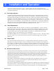
2. Installation and Operation This section contains the necessary steps to assist in getting a new flow meter/controller into operation as quickly and easily as possible. Please read the following thoroughly before attempting to install the instrument. 2.1. Receiving Inspection Carefully unpack the Hastings 201/203 series instrument and any accessories that have also been ordered. Inspect for any obvious signs of damage to the shipment.
regulators and large internal diameter plumbing help to make the system more stable. The pressure drop between the regulator and the instrument due to line resistance should be minimized. The differential pressure across the unit should be less than 6” of H2O at maximum flow. There are two 8-32 threaded holes, 0.25” deep, located on the bottom of the base that can be used to secure it to a mounting bracket, if desired (screws provided).
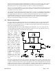
If a valve override switch is not desired, the unit is ready for use at this time. If the override switch is desired, connect the center pin of a single pole, three-position switch with the center off position to pin 8. Connect +15VDC to one end of the switch, and -15VDC to the other end. This will result in the valve being full open when +15VDC is supplied to pin 8, off when -15VDC is supplied and auto-control when there is no connection to pin 8 (OPEN-AUTO-CLOSE).
B, it then becomes a variable reference voltage for flow controller B proportional to the flow rate of flow controller A. If the set point potentiometer of flow controller B is set at 50% of full scale, and the reference voltage from flow controller A is 4.00, then the command signal going to flow controller B would be 2.00 volts (4.00 volts x 50.0% = 2.00 volts). The flow of gas through flow controller B is then controlled at 4 slpm (2.00 volts/5.00 volts x 10 slpm = 4 slpm).
2.6.8. Response to Command Changes The response of the control circuit to changes to the command signal is set at the factory for fast, stable response. Should it be necessary, the response is adjustable using the jumper labeled “JP4,” located in the center of PC-828. The fastest response to command changes is obtained when JP4 is covered by the jumper.
3. Theory of Operation This section contains an overall functional description of HFC Flow Controllers. Detailed schematics and parts lists can be found at the end of the manual in Section 6.0. In this section and other sections throughout this manual, when a power supply is mentioned, it is assumed that the customer has a Hastings Power Supply. These sections are not applicable if another type of power supply is used. 3.1.
This signal is amplified by the meter circuitry until is 0-5.00 VDC. This 5 volt output is sent back to the power supply and to the flow meter circuitry, if applicable. At the power supply the 5 volt output is sent to the terminals on the back and to the decoding circuitry in the display which converts it to a 3-digit output. The controller circuitry utilizes the Command and the Flow voltages as input signals. The 0-5VDC command signal is subtracted from the 0-5VDC flow signal creating an error signal.
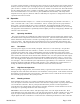
3.5. Valve: At flow rates higher than 30 slm, two valves are used in parallel. A solenoid valve is used as a pilot valve to control a much larger pneumatic diaphragm valve. The pilot valve is an “automatic metering solenoid” valve. While most solenoids operate in either the fully open or fully closed state, the automatic metering solenoid valve is designed to control flow (see Figure 3.5). A spring, connected to the plunger assembly, holds a magnetic plunger tightly against an orifice to shut off flow.
4. Maintenance This section contains service and calibration information. Some portions of the instrument are delicate. Use extreme care when servicing the flow controller. The potentiometer positions and the electrical components referred to in the troubleshooting section can be found in Section 6.0 on the electrical component layout drawing. 4.1. Authorized Maintenance With proper care in installation and use, the flow controller will require little or no maintenance.
ACTION: Shut off gas supply and power supply. Remove cover and PC board from unit. Remove sensor assembly and examine. If sensor has evidence of plugging, clean or replace as applicable SYMPTOM: Flow controller oscillates. CAUSE: Flow controller not adjusted for the dynamics of the flow system. ACTION: Check upstream and downstream pressures. The gas supply regulator should not have excessive lockup when flow shuts off.
4) Set command to 100%. Adjust SPAN (R29) pot until the flow reference reads full scale flow (5.000 VDC). NOTE: Perform this step only if a calibrated reference flow meter is available. 5) Record flow meter and flow reference outputs for flow rates of 20%, 40%, 60%, 80% and 100%. 4.3.2. Miscellaneous adjustments Periodically, during normal operation, the ZERO should be checked and adjusted when required. If system parameters change, the RESPONSE pot may require a small adjustment for optimum stability.
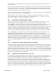
Orifice Changes: A) Determine the minimum expected upstream pressure (Pu) in PSI absolute and the maximum expected downstream pressure (Pd) in PSI absolute for full flow conditions. B) If Pu >2Pd, use formula 1; otherwise use formula 2. Where: Formula 1: Formula 2: D= 0.0028σQ Pμ D = Diameter in inches Q = Flow rate in standard liters per minute P = Pu - Pd in PSI Pu = Upstream pressure in PSIA Pd = Downstream pressure in PSIA σ = Specific gravity of gas D= 0.
STOCK NO. DESCRIPTION ..................................................................................AIR RANGE 28-13-190 Orifice 0.046...............................................................................................HFC-203 28-13-164 Orifice 0.086...............................................................................................HFC-203 28-13-163 Orifice 0.13.................................................................................................
5. WARRANTY 5.1. Warranty Repair Policy Hastings Instruments warrants this product for a period of one year from the date of shipment to be free from defects in material and workmanship. This warranty does not apply to defects or failures resulting from unauthorized modification, misuse or mishandling of the product. This warranty does not apply to batteries or other expendable parts, or to damage caused by leaking batteries or any similar occurrence.