000008345 - 15/03/2018 ASSEMBLY HANDBOOK FORTRESS FLOATING GARAGE CABINET 5GMC Stuck? Questions? We are here to help. 1-888-230-2225 help@manhattancomfort.com View our assembly video online www.manhattancomfort.
In order to ease the assembly, you should separate and identify the parts first Necessary hardware for the assembly, leveling and safety ½” STANLY * Included in the kit * Not included in the kit Do not place the parts directly onto the floor. Use a cardboard sheet or a mat to place the parts, during the separation and assembly. Stuck? Questions? We are here to help. 1-888-230-2225 help@manhattancomfort.com View our assembly video online www.manhattancomfort.
ASSEMBLY HANDBOOK WALL CUPBOARD - FORTRESS FLOATING GARAGE CABINET P8 Upper Back 3000007264 P16 Wall Fixation Support 3000007235 P1 WARNING Side 3000007298 P18 Shelf 3000007301 P4 Top 3000007299 lb Maximum weight supported by shelf 44l b 44l b P9 Lower Back 3000007366 44l b P6 Bottom 3000007300 P23 P1 Side 3000007298 Left Door 3000007304 P22 Right Door 3000007302 Hardware list F1 F5 F7 F15 F13 1000009500 1000008616 1000008301 1000008280 1000009033 Qty. 16 Qty. 3 Qty. 1 Qty.
STEP 1 F1 1 - Fit part P4 inside part P1 2 - Fit both parts in the frontal side, with F1 2x P1 P4 STEP 2 1 - Fit part P6 inside part P1 2 - Fit both parts in the frontal side, with part F1 F1 2x P1 P6 P4
STEP 3 1 - Fit part P1 to part P4 and part P6 2 - Fit part P1 to part P4 and part P6, at the frontal side, with F1 F1 4x P6 P1 P4 STEP 4 P1 1 - Turn the cupboard with the back side upwards 2 - Fit part P1 to part P4 and part P6, at the frontal side, with F1 F1 8x 180° P1 P6 P1 P4 P6 180° P1 P4 P1
STEP 5 1 - Fit part P8 into part P4 and parts P1 1 2 - Check that all fits are supported over the bolts 3 - After fitting the parts, screw the bolts until locked WARNING 2 P8 P6 Position part P8 on the P4 side for mounting the cabinet. P4 P1 3 STEP 6 1 - With the end of F13, smash the safety claw, locking part P8 to part P1. F13 WARNING P1 To avoid possible falls, this safety claw should be fixed.
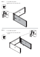
STEP 7 1 - Fit part P9 inside parts P1, P6 and P8.
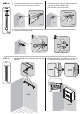
STEP 9 1 - Place part P18 diagonally so it fits inside the cupboard 2 - Lean part P18 to part P1 and place it over the F7 detailed in the illustration here below 3 - Bend the other side of part P18 down, leaning it over the left F7 F7 P4 P18 P1 P1 P6 STEP 10 1 - Align part P16 at an approximate height of 72 ½" from the floor 2 - Align the part using a level 3 - Mark the wall using holes of part P16, aided by a pencil 4 - Drill the wall where market on the wall, with the pencil using a driller with a ½”
STEP 11 2 - Pull the bushing driving it against the wall and then push the plastic ring until it leans close to the wall 1 - Insert the metal part of the bushing into the hole until it overcomes the wall. F14 Plastic ring WALL WALL WALL 3x WALL 3 - Break the bushing's rods 1 2 WALL WALL STEP 12 F5 1 - Align part P16 to the bushings and fix them with F5 WALL 2 - Fix the cupboard to part P16, held to the wall.
STEP 13 1 - To assembly the doors, fit door P22 lower hinge bolt inside the bushing fixed in part P6 2 - Then, pull the pin of door P22 upper hinge down; align the door and release the pin to fit the bushing fixed in part P4 3 - Repeat the step for part P23 1º P4 P18 P1 P1 P6 P23 STEP 14 1 -Insert product log F17 1x P22 2º