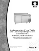
Undercounter, Prep Table and Low Boy Refrigerators and Freezers Installation, Use & Care Manual This manual is updated as new information and models are released. Visit our website for the latest manual. www.manitowocfsg.
Safety Notices Read These Before Proceeding: As you work on Manitowoc equipment, be sure to pay close attention to the safety notices in this manual. Disregarding the notices may lead to serious injury and/ or damage to the equipment. Throughout this manual, you will see the following types of safety notices: ! Warning Text in a Warning box alerts you to a potential personal injury situation. Be sure to read the Warning statement before proceeding, and work carefully.
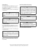
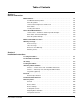
Table of Contents Section 1 General Information Model Numbers. . . . . . . . . . . . . . . . . . . . . . . . . . . . . . . . . . . . . . . . . . . . . . . . . . . 1-1 Sandwich/Salad Prep Tables . . . . . . . . . . . . . . . . . . . . . . . . . . . . . . . . . . . 1-1 Pizza Prep Tables . . . . . . . . . . . . . . . . . . . . . . . . . . . . . . . . . . . . . . . . . . . 1-1 Undercounter Refrigerators and Freezers . . . . . . . . . . . . . . . . . . . . . . . . . 1-1 Work Tables . . . . . . . . . . .
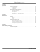
Table of Contents (continued) Section 3 Operation Sequence of Operation . . . . . . . . . . . . . . . . . . . . . . . . . . . . . . . . . . . . . . . . . . . . . 3-1 Loading Shelves . . . . . . . . . . . . . . . . . . . . . . . . . . . . . . . . . . . . . . . . . . . . . 3-1 Loading Pans . . . . . . . . . . . . . . . . . . . . . . . . . . . . . . . . . . . . . . . . . . . . . . . . 3-1 Operating Checks and Adjustments . . . . . . . . . . . . . . . . . . . . . . . . . . . . . . . . . .
Section 1 General Information Model Numbers WORK TABLES This manual covers the following models: SANDWICH/SALAD PREP TABLES Sandwich / Salad Prep Tables P-6 P-15-12 P-10-8 P-15-16 P-10-12 Super Sandwich / Salad Prep Tables ST-27-2 ST-59-3 ST-45-3 ST-59-4 ST-45-4 Super Prep Tables ST-45-12 ST-59-16 Smoothie Table FST-45-2EN PIZZA PREP TABLES Pizza Prep Tables PTA-1 PTA-2 PTA-2D PTA-3 PTA-3D PTS-1 PTS-2 PTS-2D PTS-3 PTS-3D UNDERCOUNTER REFRIGERATORS AND FREEZERS Refrigerated Undercounters — Solid Door Gl
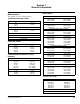
General Information Section 1 How to Read Model Numbers UNDERCOUNTERS / SANDWICH / SALAD PREP TABLE EXAMPLE Prefix Body Type Suffix P–15–16 Undercounters R - Refrigerator F - Freezer Sandwich / Salad Prep Table P - Pan top (30" depth) ST - Supertop (34" depth) 6 - 27" Wide 10 - 45" Wide 15 - 59" Wide 27 - Supertop 27" 45 - Supertop 45" 49 - Supertop 59" Undercounters E - Series Sandwich / Salad Prep Table P Series 6 - 6 Pans 8 - 8 Pans 12 - 12 Pans 16 - 16 Pans ST Series 2 - 2 Cutouts, 6 Pans each 3 -
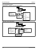
Section 1 General Information PIZZA PREP TABLE EXAMPLE Model Prefix Body Type PT–A–2 1 - 1 Door 2 - 2 Door 3 - 3 Door PT - Pizza Top Table A - Aluminum Interior A - Stainless Steel Interior Part Number 14514 2/08 1-3
General Information Model/Serial Number Location Section 1 EXCLUSIONS FROM WARRANTY The McCall data plate which includes the model number and serial number, as well as important electrical and technical information, is located on the left interior wall of the cabinet. 1. Normal start-up, maintenance, adjustments, and cleaning. For convenience and quick reference, record the model and serial numbers, voltage, and installation date in the spaces below: 3.
Section 2 Installation Instructions Pre-installation Checklist Important These instructions are of the utmost importance in assuring that the McCall cabinet operates as designed. Follow them closely. Install the cabinet in an indoor environment only. Please call your local McCall dealer or the McCall Service Department if you have any questions regarding proper installation. The air temperature entering the refrigerator or freezer condenser should be between 55°F (13°C) and 100°F (38°C).
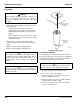
Installation Instructions Section 2 Uncrating ! Warning Never attempt to tilt the cabinet alone. Always use two or more people when tilting the cabinet to remove the shipping skid or to move it through doorways. Thread Leveling Leg into Base of Cabinet 1. Remove the bottom shipping skid using one of the methods below: - Lay the cabinet on its back, elevated and supported by wooden blocks. Remove the skid mounting bolts and separate the skid from the cabinet.
Section 2 Installation Instructions Shelf/Tray Slide Installation TRAY SLIDES (OPTIONAL) SHELVES — UNDERCOUNTER UNITS & SANDWICH/ SALAD UNITS Refrigerated pizza tables include a chrome plated steel pan or tray rack (Model RA-11-T) behind one door opening on 2- and 3-door models. All other tray slides for pizza tables and refrigerated work tables are optional accessories and are included only when ordered.
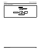
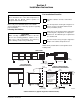
Installation Instructions Section 2 Electrical All cord-connected units must be plugged into a grounded and properly sized electrical outlet with appropriate overcurrent protection. Refer to the drawing below for electrical plug configurations. As a rule, the power lines must be enclosed inside a conduit secured to the power junction boxes on both ends. NOTE: Power installation must be in compliance with the National Electrical Code and all applicable local and state codes.
Section 2 Installation Instructions ELECTRICAL SPECIFICATIONS Product Type Undercounter Refrigerators Undercounter Freezers Sandwich/Salad Units Refrigerated Work Tables Low Boy Chef Stands Pizza Prep Tables Self-Contained Base Models R-6E, RS-6E, RSC-6E R-10E, RS-10E, RSC-10E R-15E, RS-15E, RSC-15E F-6E, FS-6E, FSC-6E F-10E, FS-10E, FSC-10E RP-6EN RP-10-6EN, RP-10-8EN, RP-10-12EN RP-15-8EN, RP-15-12EN, RP-15-16EN RST-27-2EN RST-45-2EN, RST-45-3EN, RST-45-12EN RST-59-3EN, RST-59-4EN, RST-59-16EN LTA-
Installation Instructions Section 2 Condensate Water Removal McCall cabinets are equipped with condensate vaporizer systems. Remote units use an electrically operated system. Most self-contained units use either an energy-free automatic type or an electrically-operated type. No drain connection is required. Defrost Systems GENERAL Refrigerator coils are kept below the freezing point (32°F).
Section 2 Installation Instructions ADJUSTING DEFROST DURATION The defrost cycle is terminated by a temperaturesensing switch located on the suction line, adjacent to the evaporator coil. The defrost duration is factory-set. Normally, no adjustment is required. For a longer defrost time, press down on the inner dial pointer and rotate the pointer until the desired time lines up. Important Setting the temperature control to the coldest setting may cause the coil and/or air ducts to freeze and ice up.
Installation Instructions Section 2 THIS PAGE INTENTIONALLY LEFT BLANK 2-8 Part Number 14514 2/08
Section 3 Operation Sequence of Operation Important LOADING SHELVES Uncovered food will dehydrate much more rapidly than covered food. For best food quality, always store in covered container. For maximum operating efficiency, load the shelves with space between the stored items. This allows air to circulate properly. Refer to the drawings below. LOADING PANS ! Caution Pan-top refrigerators are designed for operation with all pans in place, even if some pans are to be left empty.
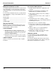
Operation Section 3 Operating Checks and Adjustments DOOR HINGE ADJUSTMENT Hinge Pin Screw 1. Loosen 2 Phillips head screws on the top and bottom hinges where the hinges fasten to the cabinet exterior front facing. 2. Firmly press the door tight to the cabinet front while re-tightening the hinge screws. Hinge Pin Hinge Mechanism Mounting Screws NOTE: For some adjustments, it may be necessary to add shims behind the hinges.
Section 4 Maintenance Cleaning Cleaning the Condenser Coil EXTERIOR Clean cabinet exterior surfaces with a solution of mild soap and water. To minimize streaking, follow with a fresh water rinse. If stainless steel becomes discolored, scrub only in the direction of the finished grain. For high shine, see your kitchen equipment dealer for a high-quality stainless steel polish. ! Caution Do not use steel wool, caustic soap, or abrasive cleaners, as these may damage the metal finish.
Maintenance Section 4 After cleaning, straighten any bent condenser fins with a fin comb. Comb Down Only CLEANING THE FAN BLADES AND MOTOR If necessary, clean the fan blades and motor with a soft cloth. If it is necessary to wash the fan blades, cover the fan motor to prevent moisture damage. CLEANING THE EVAPORATOR DRAIN PAN Fin Comb The evaporator drain pan, located at the bottom of the evaporator blower panel, should be cleaned periodically to remove any food, debris, etc.
Section 5 Before Calling for Service Troubleshooting Guide If a problem arises during operation of your refrigerator or freezer, follow the checklist below before calling service. Routine adjustments and maintenance procedures are not covered by the warranty.
Before Calling for Service Section 5 THIS PAGE INTENTIONALLY LEFT BLANK 5-2 Part Number 14514 2/08
© 2008 Manitowoc Continuing product improvements may necessitate change of specifications without notice. Part Number 14514 2/08 McCall Refrigeration, Inc. 81 West Holly Street Parsons, TN 38363, USA Ph: 731-847-5365 Fax: 731-847-9012 Visit us online at: www.manitowocfsg.