Manitoba 200 series |CE CUBER SERVICE MANUAL #* Manitoba equipment works s Division of The Townswoman Company, Inc.
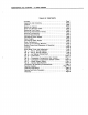
MANITOBA ICE CUBERS — A-0200 SERIES TABLE OF CONTENTS Inspection and Ingratiating. Setting Up Cabinet Serial and Electrical Plate Removing Front Anal Removing Head Section Panels Electrical Connections. . General Requirements . Connecting Power Supply Water Connecting Water Supply Drain Connections Check List for Starting System Control and Sequence of Operation Controls. barn e iin it Solid State Timer and Adjustment. Fig. Wiring Diagram .. Fig. Wiring Diagram .. Fig. 3 — Ice Making Compartment Fig.
MANITOBA ICE CUBERS ~— A-0200 SERIES Page 1 FORWARD Manitoulin Equipment Works, Division of The Manitoba Company, inc., Manitoba, Wisconsin, presents this Service Manual to assist the service man with information concerning CONSTRUCTION, INSTALLATION, and MAINTENANCE of the MANITOBA ICE MAKER. The problems of the user and the service man have been given special emphasis in the development of the latest MANITOBA Ice Machines.
Page 2 MANITOBA ICE CUBERS — A-0200 SERIES FOR YOUR PROTECTION The carrier who delivers this merchandise to your door is responsible for loss and damages. Acceptance of this shipment by the transportation company is acknowledgment that the articles delivered to them were in good condition and properly packed. It is your responsibility to file a claim with the carrier if any of the following condition exist. A. VISIBLE DAMAGE It cartons appear damaged in any form, please open at once in presence of driver.
MANITOBA ICE CUBERS — A-0200 SERIES Page 3 SERIAL AND ELECTRICAL PLATE The combined serial and electrical plate is located inside the cabinet on the partition panel above the water pump. Be sure to send the compete serial number and the model number when ailing for service or parts. On early models serial and electrical plate is located on outside right end panel. REMOVING FRONT PANEL To remove front panel, pull forward on lower edge of pane and lift up and off.
Page 4 MANITOBA ICE CUBERS — A-0200 SERIES CHECK LIST FOR STARTING MACHINE Remove tape securing the damper door, splash curtain, water pump, and float valve. Remove the corrugated packing protecting the pump during shipment. Remove compressor shipping block from beneath compressor. Turn on water, and observe that the float valve shuts off the water when the level is just below the top of the elbow. Should float require adjustment merely bend float rod carefully until desired water level is achieved.
MANITOBA ICE CUBERS — A-0200 SERIES Page & At the end of the timing sequence the relay of the solid state timer will energize. The relay’s normally closed contacts, between terminals 4 & 5, will open shutting off the water pump and condenser fan motor, and closes its normally open contacts, between terminals 3 & 4, energizing the hot gas solenoid. {The cuber can be placed in the harvest at any point during the freeze cycle by shorting across timer terminals odor terminal H & H1 depending on the make timer.
Page 6 MANITOBA ICE CUBERS — A-0200 SERIES Water Regulating Valve {(Water Cooled Only} The water regulating valve is mounted in the water infer line of the condenser. The water valve is used to control the head pressure by regulating the water flow through the condenser. The valve has an adjustment located on the head of the valve.
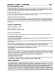
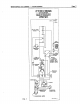
MANITOBA ICE CUBERS — A-0200 SERIES FIG. 1 PRESSURE AR,AD AND AY, 0400 SERIES AR, AD AND AY, 0200 SERIES AR AND WATER FAN ON AIR COOLED ONLY SHOWN AT BEGINNING OF FREEZE CYCLE 115 VOLT, 60 CY. T SOLO SITE TIMER 20 cur-in i 15 V.
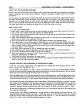
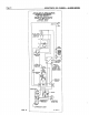
Page 8 MANITOBA ICE CUBERS — A-0200 SERIES AR AD, ANE AY 0400 SERIES AR ANO AD 0200 FAN ON AIR COOLED ONLY SHOWN AT BEGINNING OF ! FREEZE CYCLE i 230 VOLT, 50CY e 230V SUPPLY slid 5m§‘ TIMER & ~PDTEX~ cur-or | Low i PRESSURE lossless cur-m SWITCH CENTER OFF double POLE DOUBLE THROW [y TERMINAL BOARD STARTING CAPACITOR FiG.
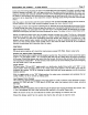
MANITOBA ICE CUBERS — A-0200 SERIES Page 9 wh FIG. 3 — ICE MAKING COMPARTMENT . Control box. . Water curtain. . Water distributor. Harvest rack. lce chute & damper door says. Water pump. Water pump mounting bracket. . Float valve & bracket. . Water sump, . Overflow elbow.
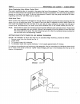
Page 10 MANITOBA ICE CUBERS — A-0200 SERIES FIG. 4 — CONTROL BOX . Main toggle switch. High pressure cut-out {water cooled only}. . Timer {solid state}, . Damper door micro switch, . Evaporator, Harvest rack. . Water curtain hook {left side).
MANITOBA ICE CUBERS — A-0200 SERIES Page 11 FiG. 8§ — COMPRESSOR COMPARTMENT {AIR COOLED) . Air cooled condenser. Condenser fan motor. . Condenser fan blade. Condenser fan motor mounting stand. Compressor. Hot gas solenoid valve. Drier. Expansion valve. Low pressure cut-in. . Thermodynamic. . Electrical supply hole. . lce water supply connection.
Page 12 MANITOBA ICE CUBERS — A-0200 SERIES FIG. 8 — COMPRESSOR COMPARTMENT (WATER COOLED) . Water regulating valve, . Water cooled condenser, Condenser water drain connection, Ice & condenser water supply, Compressor. Hot gas solenoid valve. . Expansion valve. .
Page 14 MANITOBA ICE CUBERS — A-0200 SERIES MANITOBA A-0200 SERIES HEAD SECTION GENERAL SPECIFICATIONS ICE PRODUCTION — Ibs. per 24 hours Incoming Room Temperature F * A-0200 CONDENSER WATER CONSUMPTION w200 |Water Temp. SERIES Ar 50° | 195 | 175 | 186 iCE Cooled | 70° | 175 | 160 | 145 Temperature PRODUCTION | Models | 50° | 155 | 140 | 128 Gl /24 Fir.
MANITOBA ICE CUBERS — A-0200 SERIES Page 18 60 HERTZ Cuber Model AR, AD & YA-200 AR. AD & YA-200 Series Water Cooled Series Air Cooled Compressor Model JFH1-0033-1AA JFB1-0033-1AA Compressor Voltage 115V-60Cy-1Ph 115V-80Cy-1Ph Winding Resistance Common to Run 1.2 OHMS 1.2 OHMS Winding Resistance Common to Start 2.9 OHMS 2.9 OHMS Start Capacitor Rating 233.280 MFD 110V 233-280 MFD 110V Fan Motor Model MERRILL Fan Motor Amps .
Page 16 MANITOBA ICE CUBERS — A-0200 SERIES SERVICE ANALYSIS COMPLAINT Slow harvest High head pressure High suction pressure Low suction pressure Unit noisy lce maker will not stop when full of ice Timer will not operate Small cubes or deep dipoles Machine will not cycle into harvest CAUSE Contaminated or limed water system Low ambient {(air cooled models) Water valve set too low Leaking water valve {(water cooled models) Air in system Defective water valve (water cooled models) Defective fan (air cooled mo
MANITOBA ICE CUBERS — A-0200 SERIES SERVICE ANALYSIS cont.
Page 18 MANITOBA ICE CUBERS — A-0200 SERIES CLEANING INSTRUCTIONS IN PLACE CLEANING To clean the ice cuber water system without removing the components proceed as follows: NOTE This is only recommended in locations where impurity build-up is not heavy. Remove ice cuber front panel. Shut off ice cuber. Remove ice from bin. Shut off water supply and remove water from water sump. Pour one bottle of ice machine cleaner inch sump and turn supply water on.
MANITOBA ICE CUBERS — A-0200 SERIES Page 19 SERVICE AND PARTS PROCEDURES Ordering Procedure Replacement parts for Manitoba ice machine equipment should be ordered directly from your local Manitoba lce Machine distributor, Parts are stocked by the distributor in order to provide prompt and efficient service for ice machines sold in their area. Should you encounter difficulty in locating a Manitoba distributor in your area, contact the Manitoba Service/Parts Dept.
Page 20 MANITOBA ICE CUBERS — A-0200 SERIES Ire Marine and Bin Warranty From the date of original installation, we do hereby warrant each new lce Machine and Bin to be free from defects in material and workmanship, under normal use and service, for a period of one bear, and four additional years on the hermetic motor Compressor in the lce Machine, Qur obligation under this warranty is limited solely to correcting or replacing without charge at the factory in Manitoba, Wisconsin any part or parts of this equ