Manitoba ICE MACHINES -Series G1200 SERVICE MANUAL i "‘MHz ; A N This product qualifies for the following listings: Nzt N Recycled @k We reserve the right to make product improvements at any time. Specifications and design are subject 1o change Without officer. GESTURE Part No.
MANITOBA ICE, INC, 2110 South 26th Street P.O, Box 1720 Manitoba, Wi 54221-1720 Phone: (820) 682-0161 Fax: (920) 683-7585 Web Site: www.manitowocice.com © 1999 Manitoba Ice, Inc. Li tho in U.S.A.
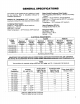
GENERAL SPECIFICATIONS This section is not intended to be a guideline to install the ice machine. Refer to Installation Manual for installation procedures.
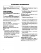
WARRANTY INFORMATION IMPORTANT Read this section very carefully for warranty explanation. (Refer to Warranty Bond for complete details.} OWNER WARRANTY REGISTRATION CARD Warranty coverage begins the day the ice machine is installed. IMPORTANT To validate the installation date, the OWNER WARRANTY REGISTRATION CARD must be mailed in. It the card was not returned, Manitoba will use the date of sale to the Manitoba Distributor as the first day of warranty coverage for your new ice machine.
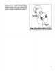
Please contact your local Manitoulin Distributor or Manitoba Ice, Inc. for further information regarding warranty coverage. (NOTE: Have model and serial numbers of ice machine available when calling. See Figure 1 for location of model and serial numbers.) MODEL/SERIAL NUMBERS DECAL {{CE MACHINE) G12SVo0! FIGURE 1. MODEL/SERIAL NUMBERS LOCATION Note: The S/N decal may be on left side of electrical box.
¥8" FPT ICE MAKING 18" WATER INLET VENT . ELECTRIC SERVICE ok hie SWITCH BOX & FPT WATER DRAIN WATER CONDENSER NET l Eater-Cooled Models} PSI MIN.J150 PSI MAx/ WATER CONDENSER i OUTLET FITTING | (wets-Cooled Models} | 1 5 DARN ) FITTING & NOTE: Refer to Re mats Installation section for cremate condenser line set and electrical connections. INSULATION WATER SERVICE VALVE WATER SERVICE VALVE IGE MAKING WATER INLET 20 FSI MIN/BO PSI MAX.
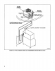
AC-1205A REMOTE CONDENSER ELECTRICAL DISCONNECT (BY CUSTOMER) DISCHARGE LINE MINIMUM AMOUNT OF TUBING ABOVE ROOF, LIQUID LINE Bore 2.50° diameter hole in roof or wall for tubing. Seal wile tar or pitch and slope to prevent entrance of moisture, 36.00" Service Loop G126V00s FIGURE 4.
ELECTRICAL. DISCONNECT (BY CUSTOMER) | MINIMUM AMOUNT OF Hula" TUBING ABBEY ROOF 7— TO SECOND ICE MACHINE Bore 4.00° diameter hole in root or wall for tubing, Seal with tar or pitch and slope to prevent entrance of moisture. IMPORTANT: Mark or tag sine sets 1 and 2 before running 1o prevent crossing of refrigeration systems. Condenser recruits are abseiled 1 and 2. 36000 Service Loop G128V00S FIGURE 8.
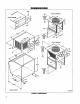
COMPONENT IDENTIFICATION 1. TERMINAL BOARD 106. RELAY BOARD 2. LOW PRESSURE CONTROL. 11, ICE SENSOR MODULE * 3. HIGH PRESSURE CONTROL 12, TRANSFORMER BOARD * 4. TOGGLE SWITCH 13, START RELAY 5. CONTRACTOR 14, START CAPACITOR 6. DUMP VALVE TIMER 18, RUN CAPACITOR 7. DELAY TIMER 16, FAN MOTOR CAPACITOR # 8. FUSE, 5 AMP 17. TERMINAL BOARD 9. RELAYS * MAY BE COMBINED INTO UNITIZED ICE SENSOR BOARD # AIR-COOLED MACHINES ONLY G128V00s FIGURE 6.
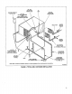
ENE SIDE COVER (COMPRESSOR START COMPONENTS BOX) . FRONT COVER (COMPRESSOR START COMPONENTS BOX} . CONTROL BOX COVER WATER FLOW CLAMPS (REGULAR SIZED CUBES ONLY) . WATER DISCHARGE TUBE WITH DUMP VALVE} . SUMP TROUGH . FLOAT VALVE . WATER PUMP (With BRACKET AND COVER) . DRAIN TUBE BRACKET . WATER CURTAIN (TWO REQUIRED) . EVAPORATOR . 1L.H SUMP THOUGH SUPPORT . SPLASH SHIELD . {CE THICKNESS CONTROL . WATER DISTRIBUTOR TUBE . BIN SWITCH (TWO REQUIRED) . SOLENOID DUMP VALVE {NOT SHOWN) G128V007 FIGURE 7.
INTERIOR CLEANING For efficient operation, lean and sanitize ice machine every six months. IMPORTANT Do not use hot water. if ice machine requires cleaning and sanitizing more frequently, consult a qualified service company to test the water quality and recommend appropriate water treatment. Before cleaning, check water dump valve for proper operation (see Cleaning Water Dump Valve, page 18). Deposits may accumulate in the valve causing leakage or restriction of water flow. REMOVAL OF PARTS FOR CLEANING 1.
REMOVE FLOAT VALVE (Figure 12) 1. Remove wing nuts from bracket and pull bracket from water trough. 2. Disconnect the water inlet tube from the float valve at the compression fitting. 8. Remove filter screen and cap. WATER INLET TUBE COMPRESSION FITTING FILTER SCREEN AND CAP REMOVE WANG NUTS G128VOI2 FIGURE 12. FLOAT VALVE REMOVAL REMOVE DISTRIBUTION TUBE {Figure 13) 1. Remove distribution jibe from the two spring clips holding it in place. 2. Disconnect the hose from the distribution tube.
REMOVE ICE THICKNESS PROBE {Figure 15) 1. Disconnect wire leads from ice sensor in control box. Be sure electrical power is disconnected. 2. Compress side of probe at top near hinge pin and disengage it from the bracket. COMPRESS HINGE PIN TO REMOVE GI2BVOS FIGURE 15. ICE THICKNESS PROBE REMOVAL REMOVE WATER TROUGH 1. Remove float valve and wale pump. 2. Disconnect water outlet hose (Figure 16). 3. Remove thumb screws and remove water rough {Figure 17).
3. Thoroughly rinse with clean water all parts and surfaces washed with the cleaning solution. 4. Add four ounces of cleaner to water trough and allow solution to circulate & maximum of 10 minutes. NOTE Incomplete rinsing of the ice thickness probe could leave residue which could cause the ice machine o go into premature harvest. For best results, brush or wipe off while rinsing and then wipe dry. NOTE Use a soft brush on excessively fifty evaporator to help remove deposits.
SANITIZING Sanitizer is used for removal of algae or slime AND AFTER USE OF MANITOBA ICE MACHINE CLEANER, It is not used for removal of lime scale or other mineral deposits. 1. Loosen two screws holding front panel in place and remove front panel. 2, Set ICE/OFF/WATER PUMP switch at OFF after ice falls from evaporator at completion of harvest cycle or set switch at OFF and allow ice to melt off evaporator, A caution Never use any type of object to force ice from evaporator as damage may result. 3.
CHECKING AND CLEANING THE WATER DUMP VALVE OPERATION CHECK 1. 2. 3. Remove front panel. Set ICE/OFF/WATER PUMP switch at ICE. Check clear plastic outlet drain hose of dump valve, Figure 18, for leakage while the ice machine is in the freeze cycle. 1f the dump valve is leaking or restricted, remove, disassemble and clean. REMOVE WATER DUMP VALVE {Figure 18} A warning Disconnect electric power to the ice machine at the electric service switch box. 1. 2. Drain water trough by removing drain plug.
DISASSEMBLE BRASS BODY WATER DUMP VALVE (Figure 20) 1. Pry off retainer on top of dump valve coll with flat tip screwdriver. coll 78 SPANNER piton {Part No. % 54-8907-3) ENCLOSING § TUBE SPRING PLUNGE T PLUNGER O-Hing RUBBER GASKET VALVE o Toby BESPOKE Place spanner tool (Townswoman Part No. 54-8907-3, available through your local Manitoba Distributor) over enclosing tube and insert pins on spanner tool into holes on bottom of tube.
ELECTRICAL SEQUENCE OF OPERATION SELF-CONTAINED AIR OR WATER COOLED FREEZE CYCLE {Churchill of Evaporator/Water Dump) With the toggle switch in the ice position, the current will flow through the high pressure cut-out and rear and front bin switches energizing the contractor coil. With the contractor energized the compressor will start. Voltage is supplied through the primary of the transformer, through the contractor and normally closed second delay timer switch.
FREEZE CYCLE {Selim-Contained Air or Water Cooled) The normally closed dump valve timer switch will open after the dump valve timer is energized continually for 20 seconds. The opening of the dump valve timer switch will DE-energize the dump valve and water will begin to flow over the evaporators, forming ice, The freeze cycle will last approximately 10-15 minutes, depending on air and water temperatures entering the ice machine. {Deter to Cycle Time Chart, page 64.
HARVEST CYCLE (NO. 1) {Self-Contained Air or Water Cooled) {Ice on Both Evaporators) The harvest cycle begins when water flowing over the ice on the evaporator contacts the probes on the ice thickness control. After a constant 6-10 seconds of water contact, the relay on the ice sensor board is energized, changing contacts #3, 45 and #6, Contact #3 — Closes to supply a secondary power {o the contractor during the entire harvest cycle.
HARVEST CYCLE {NO. 2) (Self-Contained Air or Water Cooled) (Ice Falling off Front Evaporator, Tripping Front Bin Switch/ Ice on Rear Evaporator) During the harvest mode, the hot gas raises the evaporator temperatures, causing the release of the ice from the evaporators. The ice may drop from the front, Figure 24, or rear, Figure 25, in any order or at the same time. Figure 24 shows the ice as it is falling off the front evaporator (before the rear), pushing out on the front water curtain.
HARVEST CYCLE (NO. 3) {Self-Contained Air or Water Cooled) {ice from Front Evaporator in Bin/ Ice on Evaporator Falling off, Tripping Rear Bin Switch) During the harvest mode, the hot gas raises the evaporator temperatures, causing the release of the ice from the evaporators. The ice may drop from the front, Figure 24, or rear, Figure 25, in any order or at the same time.
HARVEST CYCLE (NO.4) {Self-Contained Air or Water Cooled) (ice from Both Evaporators Has Fallen into Bin} Relays A and B are both energized after ice falls off both evaporators. With the normally open contacts of relays A and B closed, the 7-second delay timer relay is energized. After the timer is "energized" continually for 7 seconds, the timer switch will open. This interrupts the primary power supply at the transformer, DE-energizing the ice sensor relay on the unitized board.
AUTOMATIC SHUT-OFF {Self-Contained Air or Water Cooled) {Full Bin of Ice) {lce from Front Evaporator in Bin/ lce from Rear Evaporator Holding Rear Curtain Open) When ice storage bin becomes full, the last harvesting of ice cubes will not completely clear either the front or rear water curtain, holding it open, This will shut the ice machine off when it cycles back into the freeze mode. In the example below, ice has fallen off the front evaporator and cleared the front water curtain.
ELECTRICAL SEQUENCE OF OPERATION REMOTE ICE MACHINES FREEZE CYCLE (Churchill of Evaporator/Water Dump) Initial Start-Up With the toggle switch in the ice petition, current wil flow through the rear and grant bin switches to energize the liquid line solenoid. The low pressure will rise, closing the low pressure cut-out (approximately 40 psi) to energize the contractor coil which starts the compressor and the chiller.
FREEZE CYCLE {Remote Machines) The normally closed dump naive timer switch will open after the dump valve timer is energized continually switch will DE-energize the dump valve and water will begin to flow over the evaporators, storming ice. The freeze cycle will last approximately 10-18 minutes, for 20 seconds. The opening of the dump valve timer depending on air and water temperatures entering the ice machine. (Refer to Cycle Time Chart, page 84.
HARVEST CYCLE (NO. 1) {Remote Machines) {Ice on Front and Rear Evaporators) The harvest cycle begins when water flowing over the ice on the front evaporator contacts the probes on the ice thickness control. After a constant 6-10 seconds of water contact, the relay on the ice sensor board is energized, changing contacts #3, #5 and #6.
HARVEST CYCLE (NO. 2} {Remote Machines) {Ice Falling off Front Evaporator, Tripping Front Bin Switch/ Ice on Rear Evaporator) During the harvest mode, the hot gas raises the evaporator temperatures, thus causing the release of the ice from the evaporators. The ice may drop from the front, Figure 31, or the rear, Figure 32, in any order, or at the same time, Figure 31 shows the ice as it is falling off the front evaporator (before the rear), pushing out on the front water curtain.
HARVEST CYCLE (NO. 3) {Remote Machines) {ice from Front Evaporator in Bin/ ice on Rear Evaporator Falling off, Tripping Rear Bin Switch) During the harvest mode, the hot gas raises the evaporator temperatures, causing the release of the ice from the evaporators. The ice may drop from the front, Figure 31, or the rear, Figure 32, in any order or at the same time. Figure 32 shows the ice as it is falling off the rear evaporator (after ice has fallen off the front), pushing out on the rear water curtain.
HARVEST CYCLE {NO. 4) {Remote Machines) {lce from Both Evaporators Has Alien into Bin) Re lays A and B are both energized after ice falls off both evaporators. With the normally open contacts of relays A and B closed, the 7-second delay relay is energized. After the timer is *energized"” continually for 7 comprise, the timer switch will open. This interrupts the primary p wore supply at the transformer, DE-energizing the ice sensor relay on the unitized board.
AUTOMATIC SHUT-OFF {Remote Machines) (Full Bin of lce} {ice from Front Evaporator in Bin/ Ice from Rear Evaporator Holding Rear Curtain Open) When the ice storage bin becomes full, the last harvesting of ice cubes will not completely clear either the front or rear Walter curtain, holding it open. This will shut the ice machine off when it cycles back into the freeze mode. In this example, ice has fallen off the front evaporator and cleared the front water curtain.
WATER SYSTEM SEQUENCE OF OPERATION SELF-CONTAINED OR REMOTE MACHINES WATER SYSTEM REAR REAR EVAPORATOR EVAPORATOR = FRONT EVAPORATOR | EVAPORATOR WATER INLET WATER INLET DUMP WATER DUMP WATER / WATER SUPPLY VALVE PUMP ¢/ suppl Y i 1/ [0 FLOAT FLOAT VALVE VALVE t r OVERFLOW 70 70 TUBE DRAIN DRAIN 8Y1103 8V1106 FIGURE 39. CHURCHILL WATER FLOW SEQUENCE Churchill Water Flow Sequence The water from the sump trough is pumped through the energized dump valve and down ths drain.
REFRIGERATION SYSTEM SEQUENCE OF OPERATION SELF-CONTAINED AIR OR WATER COOLED CHURCHILL AND FREEZE CYCLE B HEAT EXCHANGE EXPANSION VALVE HOT CAS SUCTION LINE EVAPORATOR i eerrsccceersccsceraerrenes 4 q /i COMPRESSOR DISCHARGE LINE SOLENOID VALVES REAR AR/WATER COOLED CONDENSER FIGHT PRESSURE VAPOR HIGHLIGHT PRESSURE LIQUID [J Low PRESSURE LIQUID BARLOW PRESSURE VAPOR BVi094 FIGURE 42.
HARVEST CYCLE {Self-Contained or Water Cooled) SUCTION LNE EVAPORATOR COMPRESSOR AR/WATER CODED CONDENSER [J6GH PRESSURE VAPOR MIGHT PRESSURE LIQUID f Slow PRESSURE LIQUID BELOW PRESSURE VAPOR $Vi086 FIGURE 45. HARVEST CYCLE ICE OFF REAR EVAPORATOR BEFORE FRONT EVAPORATOR Harvest Cycle Refrigeration Sequence The harvest cycle begins with hot gas flowing through both energized hot gas valves to heat the evaporators (Figure 43).
REFRIGERATION SEQUENCE OF OPERATION REMOTE ICE MACHINES CHURCHILL AND FREEZE CYCLE HEAT FRONT. EXCHANGE, EVAPORATOR SUCTION LINE EVAPORATOR COMPRESSOR = 8 DISCHARGE LINE R PUMP HARVEST Do PRESSURE Solenoid REGULATING VALVE BRIER RECENTER RECEIVER SERVICE i VALUE eSS N HEAD PRESSURE CONTROL REMOTE CONDENSER HIGH PRESSURE VAPOR HIGH PRESSURE LOUD SLOW PRESSURE LIQUID SLOW PRESSURE VAPOR 5v1098 FIGURE 46.
HARVEST CYCLE {Remote Machines) HEAT FRONT N P S EXCHANGE EVAPORATOR 8 EVAPORATOR EXPANSION EXPANSION ; N ! VALVE VALVE SUCTION LINE X EVAPORATOR COMPRESSOR H § DISCHARGE LINE e S ’ value PULP HARVEST R, REMOTE Do PRESSURE SOLENOID USER SOLENOID REGULATING VALVE =2 DRIER ! HEAD | VALVE CONTROL : [WHICH PRESSURE VAPOR MIGHT PRESSURE LIQUID SLOW PRESSURE LIQUID SLOW PRESSURE VAPOR BVH01 FIGURE 49.
AUTOMATIC SHUT-OFF {Remote Machines) The liquid line solenoid (pump down solenoid) is DE-energized and the compressor continues to run, The compressor pumps refrigerant out of the low side of the ice machine and into the high side past the check valve. The low pressure cut-out control opens when the low side pressure reaches 12-17 psi. When the cut-out control opens the compressor is DE-energized.
SERVICE DIAGNOSTIC CHART Symptom Possible Cause Corrective Action ice machine will not run, ICE/OFF/WATER PUMP switch. a. Not in iCE position. b. Defective/miswired. High pressure cut-out control tripped. a. Condenser water pressure fow or off {(water cooled). Condenser water temperature above 90°F (water concealed. b. Dirty condenser (air cooled). Refrigerant overcharge. High side refrigerant lines or component plugged. {. Headmaster control valve defective. g. H.P.C.O. control defective. h.
Symptom Possible Cause Corrective Action Fan motor will not start {self contained air cooled machines). Defective fan cycling control. Defective fan motor. Check fan cycling control, page 46. Check fan motor, Ice machine will not cycle into harvest, Refer to page 54 for Diagnostic Procedures, Ice machine repeatedly cycles into harvest with fettle or no ice formation. Refer to page 55 for Diagnostic Procedures.
COMPONENT FUNCTION, SPECIFICATIONS AND CHECK PROCEDURES BIN SWITCHES Function 1. The front evaporator or rear evaporator bin switch is controlled by movement of the corresponding water curtain {see Water Curtain, page 48). 2. The front bin switch movement energizes relay A and the rear bin switch movement energizes relay B during the harvest cycle. 3. Either bin switch may be held open to shut the ice machine off when the bin is full of ice Specifications Single pole, double throw, normally closed.
Specifications Cut-out — (opens) 175 psi. Cut-in — (closes) 225 psi. Check Procedures 1. Verify fan motor winding are not open or grounded and tan spins freely. 2. Connect manifold gauges to ice machine. Refer to page 73. 3. Hook voltmeter in parallel (across) to the fan cycle control, leaving wires attached. 4. Pressure above 225 psi — read 0 volts and fan should be running. Pressure below 175 psi — read line voltage and fan should be off.
ICE THICKNESS PROBE Function Maintain correct ice thickness. ice Thickness Check {Figure 53) Be sure the water curtain is in place o prevent water from splashing out of water trough. Inspect bridge connecting the cubes. The bridge should be approximately 1/8" thick. The ice thickness probe is factory set to maintain 1/8 inch ice bridge thickness. if adjustment is necessary, adjust as follows: 1.
WATER CURTAIN Function 1. Prevents water from splashing into bin. 2. Acts as lever fo depress and release bin switches as ice falls from the evaporator. Check Procedure 1. Pull bottom of water curtain (Figure 55) away from evaporator, then release. Curtain should fall back 10 evaporator. BIN SWITCH LEVER CURTAIN HANGER {Lift tabs with thumbs wheels filing hanger) LOOSEN HANGER SCREWS AND ADJUST HANGERS TO ELIMINATE SIDE TO SIDE MOVEMENT WATER CURTAIN CURTAIN P G128V0s5 FIGURE 55. WATER CURTAIN CHECK 2.
DUMP VALVE TIMER Function The S.C.R. switch is normally closed and energizes the dump valve for the first 20 seconds of the freeze mode. This preschools the evaporator while flushing the water from the last freeze mode. The timer is factory set at 20 seconds and should require no further adjustment. Specifications 208-230 vomit, 50760 Hertz. Normally closed silicon rectifier switch. Check Procedure Clip voltmeter leads across switch terminals #1 and #2. Keep all wire leads attached. u $V1093 FIGURE 56.
7-SECOND DELAY TIMER Function The normally closed 8.C.R. switch is in series with the primary of the transformer. The timer resets the ice machine to the freeze mode by momentarily interrupting the power to the transformer. The time delay is initiated after relays And B are both energized through the front and rear bin switches. On completion of delay period (7 seconds) the 5.C.R. switch opens and the transformer power supply is interrupted. This cycles the ice machine back into the freeze mode.
LOW PRESSURE CUT-OUT CONTROL {Remote Machines Only} Function 1. Energizes and DE-energizes the contractor to start and stop the ice machine. 2. Drop in suction pressure opens the low pressure cut-out control. Specifications Cut-out — 15 psi £ 3. Cut-in— 40 psi £ 3. Check Procedure 1. Connect manifold gauges, page 73. 2. Connect a voltmeter in parallel! (across) wires leaving the cut-out control, 3. Set toggle switch to OFF position.
ELECTRONIC CONTROL CIRCUITRY The ice machine uses either a transformer board with a plug-in sensor module or a unitized sensor board to control the ice thickness and initiate the harvest cycle. See Figure 58, The transformer board and sensor modifiable are not available as replacement parts. If either fails, replace both with a unitized sensor board, Refer to ice machine Electrical Sequence of Operation {see Table of Contents) for operation of control circuitry.
DIAGNOSING ELECTRONIC CONTROL CIRCUITRY IMPORTANT The transformer board and sensor module are not available as replacement parts. If either fails, replace both with Unitized Sensor Board. A caution THESE PROCEDURES MUST BE PERFORMED BY A QUALIFIED TECHNICIAN, Do not make adjustments or turn the ice machine off until the malfunction is identified. The problem may be intermittent and you may lose the opportunity fo make the checks while it is malfunctioning.
MANITOBA ¢ g ICE SENSOR NOTE: BOARD MUST BE IN ICE MACHINE WITH ALL WIRES ATTACHED, @ESVOS1 FIGURE 60. UNITIZED SENSOR BOARD Step 3: Disconnect wires from terminals 20 and 21 on board. Connect jumper wire to terminals 20 and 21, Figure 60. Does the ice machine go into the harvest cycle? IF NO: Install new unitized sensor board, It ice machine you are working anus transformer board/sensor module system, replace both components with unitized sensor board.
DIAGNOSING SINGLE (1) PHASE COMPRESSOR AND START COMPONENTS ELECTRICALLY USE COPPER TORSION PONCY 10 (eta MOTOR CODE 1 3 COMPRESSOR Bristol M53A223BBC OHM VALUES* LOCKED ROTOR AMPS 8 or SR 0.601 1.800 2401 27.0 Amps 0.570 2030 2600 97.0 Amps *Gator code determined by 6th digit in serial burner. **Compressor at room temperature. 8108704 FIGURE 61. ONE PHASE COMPRESSOR AND START COMPONENTS SCHEMATIC Perform the following tests, in sequence, using quality, calibrated volt-ohmmeter. 1.
e. Check winding resistance against values given in chart. The resistance values from C-R and C-$ added together should equal the reading from Sto R. 5. Capacitor check {fun and start): a. Capacitors may show visual evidence of failure, such as a bulged terminal end or a ruptured membrane. However, do not assume a capacitor is good just because there are no visual signs of failure. An effective test is to disconnect leads to the capacitor in the ice machine and connect them to a good capacitor. ¢.
DIAGNOSING THREE (3) PHASE COMPRESSOR AND START COMPONENTS ELECTRICALLY T-72 TI.T8 T-18 122 1.22 122 “Compressor at room temperature COMPRESSOR Bristol MEIA223DBL. OHM VALUES* LOCKED ROTOR AMPS 70.0 Rps 8108708 FIGURE 62. THREE PHASE COMPRESSOR AND START COMPONENTS SCHEMATIC Perform the following tests, in sequence, using a quality, calibrated volt-ohmmeter. 1. Verity electric power to thee ice machine at time of compressor start-up is 208/230 V 2.
Disconnect wires from compressor terminals. Check continuity between terminals T1 to T2, T1t0 T3, and T210 T3. Continuity — see step d. No continuity -— open winding. Replace compressor. Check continuity at each terminal, T1, T2, and T3, to compressor shell. Terminals {o shell of compressor. Continuity — compressor grounded. Replace compressor. No continuity — compressor not grounded. Check winding resistance against values given in Figure 62. The values of all readings should be equal.
REFRIGERATION AND OTHER NON-ELECTRICAL PROBLEMS INTRODUCTION TO THE SIX-STEP DIAGNOSTIC PROCEDURE 6. FINAL ANALYSIS i 5. REFRIGERATION INSPECTION CHECKS 2, IE 4 WATER PRODUCTION SYSTEM \ 3.1CE Fill PATTERN G6sVOse FIGURE 63, SIX-STEP DIAGNOSTIC PROCEDURE The Six-Step Procedure (Figure 63) is designed to increase the accuracy of your service call, while decreasing the time required to identify any problems. 60 Refrigeration components will react and try to compensate for non refrigeration component problems.
STEP 1 — VISUAL INSPECTION Talk to the ice machine user to identify the perceived problem(s). The user's information could help you start in the right direction and may be a determining factor in your final diagnosis. Following are a few questions to consider when talking to the ice machine user: « When is the ice machine malfunctioning? (Night, day, all the time, during freeze cycle, harvest cycle, etc.) When do you notice low production? (One day a week, every day, weekends, etc.
STEP 2 — ICE PRODUCTION The amount of ice a machine produces is in direct relationship to water and air temperatures, this means an ice machine produces more ice in a 70°F room with 50°F water than in a S0°F room with 70° F water. 1CE PRODUCTION CHARTS {Lbs. of lce per 24 Hours) Water-Cooled Water Temp. °F Air Temp. 1280 1150 1010 80 1280 1140 1000 90 1270 1130 990 100 1260 1120 980 Air-Cooled Water Temp. °F Air Temp.
STEP 3 — ICE FILL PATTERN The fill patterns on the evaporators are normal when the ice thickness is a uniform 1/8 inch from top 10 bottom and side to side. {The ice bridge is the inter-connecting waffle between the cubes. Refer to page 48.) The water should freeze on the entire evaporator at the same time and both evaporators at the same rate. Ice forming on the bottom of an evaporator then working its way up to the top is hat normal and must be noted as “thin on top and thick on bottom.
STEP 5 — REFRIGERATION The refrigeration section requires taking several checks 1o gather information. NOTE Only proceed to Refrigeration System Step § after Steps 1-4 have been thoroughly checked and a final diagnosis could not be determined. CYCLE TIME CHART NOTE Ta calculate total cycle time, add harvest time to freeze time listed in charts. Ambient Freeze Time Temp. Water Temp.
Step S5A — Analyze Discharge Pressure B. Using the Operational Pressure Chant, page 64, determine if the discharge pressure is correct for the ambient temperature the ice machine is located in. C. If discharge pressure is not within normal range, refer to the appropriate chart below. Record findings on Refrigeration Diagnostic Chart, page 71. A. It discharge pressure Is within normal range, proceed to Step 5B to analyze suction pressure.
Step 5B — Analyze Suction Pressure NOTE Discharge pressures must be analyzed before suction pressure. To analyze suction pressure you must compare the Operational Pressure Hart, page 64, to the Cycle Time Chart, page 64. The suction pressure gradually drops as ice forms throughout the freeze cycle. A. Normal suction pressure: proceed through Six-Step Procedure. (Example: 33 psi after 9 minutes into the freeze cycle is normal at 90°F air and 70°F water.
SUCTION PRESSURE LOW Eliminate the possible problems in the order listed on chart and follow appropriate corrective measure. Possible Problem Actual Findings Corrective Measure 1. Low load conditions, 2. Water area problem. 3. Tubing separating from backside of evaporator. 4. Plugged nonrestrictive in Relocate ice machine to location within guidelines. Refer to Step 4. Replace evaporator. Repair — refer to Evacuation/ liquid fine. Charging Procedures, page 78. §. TXV is starving/low on charge.
HEAT Lo~ EXCHANGE FRONT EVAPORATOR REAR EVAPORATOR SUCTION LINE FROM EVAPORATOR B L ( HOT GAS VALVE CHECK 5 MIN. INTO FREEZE: FEEL INLET HOT GAS VALVE COMPARE TO COMPRESSOR DISCHARGE LINE \ DISCHARGE LINE Expansion VALVE EXPANSION | | fi VALVE ] 4 ~ HOT GAS SOLENOID VALVES TXV OPERATIONAL CHECK 5 MIN. INTO FREEZE: COMPARE TEMPERATURES AT INLET OF BOTH EVAPORATORS AIR WATER COOLED G COMPRESSOR RECEIVER NOTE: SELF-CONTAINED DIAGRAM SHOWN. CHECKS ARE THE SAME FOR REMOTE MODELS sV110¢ FIGURE 64.
2) The suction pressure will be lower than normal, 3) Thrice pattern {(page 63) will be thin on top and thick on bot torn of evaporator fed by a starving TXV and normal on evaporator fed by a good TXV. b. Symptoms of a flooding naive: 1) lce production will be low or ice machine may not make ice. 2) The suction pressure will be higher than normal. 3) The ice pattern will be thick on top and thin on bottom of evaporator fed by flooding TXV and normal on evaporator fed by a good TXV, 4.
STEP 6 — FINAL ANALYSIS Thoroughly following the first § steps has eliminated all refrigerant problems. The Refrigeration Component Chart will verify what is causing the problem. Fill out the chart using the following procedures: 1. Based on the symptoms found while performing Steps 1 through 5, fill in the Actual Findings column. 2. Each time the actual finding is the same as the characteristic listed to the right of a step number, put a check in the appropriate box.
DUAL EVAPORATOR ICE MACHINE REFRIGERATION COMPONENT DIAGNOSTIC CHART This chart is used with a detailed outline of each of the Six Steps listed. Failure to follow the details of each step in order will result in a misdiagnosis. HOT GAS VALVE LEAKING TXV TXY INEFFICIENT ACTUAL STEPS {not wide-open STARVING FLOODING COMPRESSOR FINDINGS 1.
HEADMASTER CONTROL VALVE {Remote Machines) Manitoba remote systems require Headmaster Control Valves with special settings. Replace defective Headmaster Control Valves only with “original” Manitoba replacement parts. Operation The R-502 Headmaster Control Valve has anon-adjustable setting of 185 psi (+ 10). At ambient temperatures of 70°F and above refrigerant flows through the naive from the condenser to the receiver inlet.
HOW TO USE MANIFOLD GAUGES Manifold gauges must be installed and removed proper. Backseat (open) both high and fow side service Iy to ensure no refrigerant contamination or loss occurs, valves at the ice machine. INSTALLING MANIFOLD GAUGES 3. With machine operating, read high and low side pressures on gauges. REMOVAL OF MANIFOLD GAUGES G126VoE5 FIGURE 65. INSTALLING MANIFOLD GAUGES 1. Connect high side line to high side service valve at ice machine. See Figure 65. FIGURE 66.
TXV INSTALLATION Correct expansion valve installation is essential for proper operation. Some key points to remember when installing a valve include: SOLDERING IN VALVE Wrap the TXV with a wet rag or another heat sink. This will prevent damage 10 the valve from overheating. CAPILLARY TUBES OFF TOP OF BULBS INSULATE BETWEEN SUCTION LINES SO THAT BLUES AND SUCTION LINES CLAMPS DO NGT LEAVING EVAPORATORS svi110 FIGURE 67.
ALSO REFRIGERATION SOLENOID VALVES (200 RB SERIES) REPLACEMENTS The internal parts of Alcoa solenoid valves (200 RB Se rigs) are replaceable without change out of the brass body. Rebuild kit, Manitoba part No. 24-0460-3, is available for these Alcoa solenoid valves. The rebuild kit includes the plunger, spring, O-ring, and piston assembly. A solenoid valve which has a damaged seat or is stuck open or closed can, in most cases, be repaired by installing the rebuild kit.
LEAK CHECKING CONDENSER AND WATER REGULATING VALVE IMPORTANT Both the condenser and water regulating valve must be leak checked. LEAK CHECKING CONDENSER 1. Set ICE/OFF/WATER PUMP switch at OFF. 2. Turn off incoming condenser water supply. 3. Disconnect incoming condenser water inlet and outlet lines. 4, Disconnect water regulating valve from condenser. 5. Blow water out of condenser with compressed air. NOTE Watering the condenser may cause an electronic leak detector to give a false signal. 6.
REMOVAL FROM INTERNATIONALIZATION ‘You must take special precautions if the ice machine is to be removed from service for extended periods or exposed o ambient temperatures of 32°F or below. A CAUTION IF WATER IS ALLOWED TO REMAIN IN THE MACHINE IN FREEZING AMBIENT TEMPERATURES, IT WILL FREEZE, RESULTING IN SEVERE DAMAGE TO COMPONENTS. A FAILURE OF THIS NATURE IS NOT COVERED BY WARRANTY. Self-Contained Air-Cooled Machines 1. Disconnect electric power at circuit breaker or electric service switch. 2.
EVACUATION AND RECHARGING REMOVAL OF REFRIGERANT Do not purge the refrigerant to the atmosphere. Recapture refrigerant using recovery equipment by following specific manufacturer’s recommendations. IMPORTANT Manitoba Ice, Inc. assumes no responsibility for use of recycled refrigerant. Damage resulting from the use of contaminated recycled refrigerant is the sole responsibility of the servicing company.
CLOSED CLOSED OPEN OBSERVES Open high side manifold gauge valve, backseat high side service valve. Open charging cylinder and add measured nameplate charge through discharge service valve. Allow system to “settle” for 2 or 3 minutes after charging. Place ice machine toggle switch in ICE position, close high side on manifold gauge set, and add remaining vapor charge through suction service valve (if necessary).
EVACUATION AND RECHARGING OF REMOTE SYSTEMS Before proceeding, determine severity of contamination and cleanup procedures, page 82. 1. Evacuation of remote systems requires connection at four points for complete evacuation as follows. Refer to Figure 73, a. Suction side of compressor through suction service valve. b. Discharge side of compressor through discharge service valve. c. Receiver outlet service valve. (Evacuates area between head pressure control valve in condenser and pump-down solenoid.} d.
SEVERE SYSTEM CONTAMINATION GENERAL it is important to read and understand the following text regarding severe system contamination. The purpose is to describe the basic requirements for restoring contaminated systems to reliable service. IMPORTANT Manitoba Ice, Inc. assumes no responsibility for the use of recycled refrigerant. Damage resulting from the use of recycled refrigerant is solely the responsibility of the servicing company.
MILD SYSTEM CONTAMINATION LEAN-UP PROCEDURES Replace failed components if applicable. If compressor checks good, change oil in compressor. Replace liquid line drier. Follow normal evacuation procedure, page 78, except replace the evacuation step with the following: NOTE If contamination is from moisture, the use of heat lamps or heaters is recommended during evacuation.
3-PHASE WIRING DIAGRAMS (380/220 V,3Ph,650H2) .. 35 WATER SYSTEM SEQUENCE OF OPERATION — SELF-CONTAINED OR REMOTE MACHINES Water SYSTEM REFRIGERATION SYSTEM SEQUENCE OF OPERATION — SELF-CONTAINED INTERCOLLEGIATE Precambrian Freeze Cycle Harvester REFRIGERATION SEQUENCE OF OPERATION — REMOTE ICE MACHINES 40 Churchill and Freeze Cycle .. 40 Harvester.
ALSO REFRIGERATION SOLENOID VALVES REPLACEMENTS .. .. 75 LEAK CHECKING CONDENSER AND WATER REGULATING VALVE 76 REMOVAL FROM INTERNATIONALIZATION 77 EVACUATION AND RECHARGING 78 Removal of Refrigerant ...t .. ..