Model 11M Root Beer System Refrigeration Unit Installation, Use & Care Manual This manual is updated as new information and models are released. Visit our website for the latest manual. www.manitowocfsg.
Safety Notices Read These Before Proceeding: As you work on Manitowoc equipment, be sure to pay close attention to the safety notices in this manual. Disregarding the notices may lead to serious injury and/ or damage to the equipment. Throughout this manual, you will see the following types of safety notices: ! Warning Text in a Warning box alerts you to a potential personal injury situation. Be sure to read the Warning statement before proceeding, and work carefully.
Table of Contents (continued) Section 1 General Information Read This Manual . . . . . . . . . . . . . . . . . . . . . . . . . . . . . . . . . . . . . . . . . . . . . . . . . 1-1 Unit Inspection . . . . . . . . . . . . . . . . . . . . . . . . . . . . . . . . . . . . . . . . . . . . . . . . . . . 1-1 Model Numbers. . . . . . . . . . . . . . . . . . . . . . . . . . . . . . . . . . . . . . . . . . . . . . . . . . . 1-1 How to Read a Model Number . . . . . . . . . . . . . . . . . . . . . . . . . . . . . .
Table of Contents (continued) Refrigeration Unit Installation . . . . . . . . . . . . . . . . . . . . . . . . . . . . . . . . . . . . . . . 2-12 Positioning of Refrigeration Unit . . . . . . . . . . . . . . . . . . . . . . . . . . . . . . . . . 2-12 Equipment Placement . . . . . . . . . . . . . . . . . . . . . . . . . . . . . . . . . . . . . . . . . 2-12 Electrical Connections . . . . . . . . . . . . . . . . . . . . . . . . . . . . . . . . . . . . . . . . . 2-12 Tower Installation . . . . . . . . .
Table of Contents (continued) Section 4 Maintenance Sanitizing. . . . . . . . . . . . . . . . . . . . . . . . . . . . . . . . . . . . . . . . . . . . . . . . . . . . . . . . 4-1 Beverage System Cleaning . . . . . . . . . . . . . . . . . . . . . . . . . . . . . . . . . . . . 4-1 Bag-In-Box System Sanitation . . . . . . . . . . . . . . . . . . . . . . . . . . . . . . . . . . 4-1 Figal Beverage System . . . . . . . . . . . . . . . . . . . . . . . . . . . . . . . . . . . . . . . .
Table of Contents (continued) THIS PAGE INTENTIONALLY LEFT BLANK iv Part Number 020001552 5/11
Section 1 General Information Section 1 General Information Read This Manual Model Numbers Manitowoc Food Service developed this manual as a reference guide for the owner/operator and installer of this equipment. Please read this manual before installation or operation of the machine. A qualified service technician must perform installation and start-up of this equipment, consult Section 5 within this manual for service assistance.
General Information Section 1 Accessories Depending on store type and location, various optional equipment (such as CO2 Panel, water filter kit, water booster kit, etc.) may be added to this system. Install and connect any optional equipment in the desired location according to the installation instructions provided with these kits/equipment. Special Applications ATTENTION: MARINE INSTALLATIONS ! Warning This unit is for use on vessels over 66 ft (20 m) in length.
Section 1 General Information Serial Plate Location Warranty Information Consult your local MBE Distributor for terms and conditions of your warranty. Your warranty specifically excludes all beverage valve brixing, general adjustments, cleaning, accessories and related servicing. Your warranty card must be returned to MBE to activate the warranty on this equipment. If a warranty card is not returned, the warranty period can begin when the equipment leaves the MBE factory.
General Information Section 1 THIS PAGE INTENTIONALLY LEFT BLANK 1-4 Part Number 020001552 5/11
Section 2 Installation General UNPACKING AND INSPECTING Carefully inspect the refrigeration unit immediately upon unpacking. Verify the equipment and parts received against the Bill of Lading. Locate all items according to packing list and inspect for possible damage caused by shipping. Notify the appropriate carrier if necessary and contact MBE immediately for replacement of parts if discrepancies exist. 1.
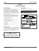
Installation Section 2 Dimensions and Clearances Wall 12" (30.5 cm) minimum 6" (15.2 cm) minimum J 18" (45.7 cm) minimum Wall Wall Electrical Junction Box Control Switches 3-7/8" (9.8 cm) Diameter Air Flow 6" (15.2 cm) Diameter Chase minimum Top View Electrical Junction Box 18" (45.7 cm) minimum Ceiling Conduit to Dispensing Towers D W CO2 Regulator Panel (Optional) Incoming Syrup Supply Lines Drain Connection P N Side View Front View • Refrigeration units require stand or 6" (15.
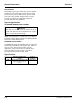
Section 2 Installation REMOTE CONDENSER OPTIONAL 38.00" (96.52 cm) 34.00" (86.36 cm) 30.00" (76.20 cm) 27.94" (70.97 cm) 1.50" (3.81 cm) 29.50" (74.93 cm) 29.16" (74.06 cm) 6.50" (16.51 cm) 6.00" (15.24 cm) 3.50" (8.89 cm) OPTIONAL 20.00" (50.80 cm) 16.00" (40.64 cm) 12.00" (30.48 cm) 14.62" (37.13 cm) 4.00" (10.16 cm) BLADE TOWER 11.86" (30.1 cm) .75" (1.9 cm) 9.68" (24.6 cm) 5" (12.7 cm) 3" (7.6 cm) 17.3" (43.9 cm) 3.29" (8.4 cm) 7.39" (18.8 cm) 10.75" (27.3 cm) 1.75" (4.4 cm) 4.88" (12.
Installation Section 2 Safe Installation Dos and Don’ts • DO NOT exhaust CO2 gas (example: syrup pump) into an enclosed area, including all types of walk-in coolers, cellars, and closets. • DO NOT throw or drop a CO2 cylinder. Secure the cylinder(s) in an upright position with a chain. • DO NOT connect the CO2 cylinder(s) directly to the product container. Doing so will result in an explosion causing possible death or injury. It is best to connect the CO2 cylinder(s) to a regulator(s).
Section 2 Installation Location Requirements CLEARANCES Control Side (Right) 18" (45.7 cm) Tower Connection Side (Left) 12" (30.5 cm) Back Side 6" (15.2 cm) Ceiling 18" (45.7 cm) ! Warning Carbon Dioxide (CO2) displaces oxygen. Exposure to a high concentration of CO2 gas causes tremors, which are followed rapidly by loss of consciousness and suffocation. If a CO2 gas leak is suspected, particularly in a small area, immediately ventilate the area before repairing the leak.
Installation Section 2 Installer Instructions Ambient Location Requirement Important The remainder of these instructions is to be completed by an authorized Multiplex Installer. These equipment instructions are intended to assist qualified personnel in the unpacking, locating and the initial operation of the Multiplex Beverage Equipment Post Mix Refrigeration Unit. This equipment is rated for indoor use only. It will not operate in sub-freezing temperature.
Section 2 Installation GROUNDING INSTRUCTIONS ! Warning ! Warning The beverage/ice machine must be grounded in accordance with national and local electrical codes. This appliance must be grounded. In the event of malfunction or breakdown, grounding provides a path of least resistance for electric current to reduce the risk of electric shock. This appliance is equipped with a cord having an equipment-grounding conductor and a grounding plug.
Installation Section 2 Plumbing/Water Supply Bracket PLUMBING POTABLE WATER Model 11M Required Water Pressure Drain Connections Water Supply 40 – 70 psig (2.8 – 4.9 bar) 3/4" ID within 6 ft (2 m) 3/8" ID EVA Line A 1" (2.54 cm) ID copper inlet water line equipped with a 3/4" (1.905 cm) FPT sweat adapter with shut-off must be supplied by plumber at rear of equipment. Appropriate floor drains must be provided within 6 ft (183 cm) of each unit installed.
Section 2 Installation PLUMBING CIRCUIT DIAGRAMS — MODEL 11M ROOT BEER Single Tower Plumbing Installation Kit (020001441) 020001403 00861302 Primary Carb Pump Pressurized Filtered Water Supply Carb Tank Circ Pump Part Number 020001552 5/11 2-9
Installation Section 2 Model 11M Root Beer Dual Tower Plumbing Installation Kit (020001441) 020001403 00861302 Tee Kit (020001411) Primary Carb Pump Pressurized Filtered Water Supply Carb Tank Circ Pump 2-10 Part Number 020001552 5/11
Section 2 Installation Model 11M Root Beer Three Tower Plumbing Installation Kit (020001441) 020001403 00861302 Tee Kit (020001411) Tee Kit (020001411) Primary Carb Pump Pressurized Filtered Water Supply Carb Tank Circ Pump Part Number 020001552 5/11 2-11
Installation Section 2 Refrigeration Unit Installation POSITIONING OF REFRIGERATION UNIT Before proceeding with installation, verify that all requirements for roof mounted Remote Condenser Units have been satisfied (if applicable). Refer to the instructions on installing the Remote Condenser supplied with the unit. If unit is to rest on floor, locate four 6" (15.2 cm) adjustable legs (optional). Screw and tighten legs into the bottom of the refrigeration unit.
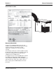
Section 2 Installation 2. Connect the circulating water by connecting one line to the circulating pump outlet line (3/8” barb) and clamp in place. Connect the other line to the bulkhead return fitting located by the agitator motor (3/8” barb) and clamp in place. Connect CO2 supply inside unit. CO2 Supply & Gauge 3. Connect the conduit lines.
Installation Section 2 Connect the drain Locate the drain hose, bracket and the two (2) screws provided in the installation kit. Attach the drain hose to the water bath overflow tube located on the bottom of the refrigeration unit. Route drain hose to a floor drain (See Below). Bracket 6. Route the numbered syrup lines to the syrup supply (syrup tanks, Bag-In-Box, or bulk syrup). Do not attach lines to syrup supply at this time. Lines will be attached to syrup supply after system is tested for leaks. 7.
Section 2 Installation Model 11M Connections Opening for Conduit Supply Lines Drain Hose Part Number 020001552 5/11 John Guest Fittings Control Switches 2-15
Installation Section 2 INSULATING CONNECTIONS 1. Make sure all exposed carbonated water and syrup lines are well insulated on towers to conduit, conduit junctions, refrigeration unit to conduits, and drivethrough junction. 2. To insulate the above, use the leftover conduit sections and tape. 3. Cut the conduit sections to fit snugly over the exposed lines and fittings. A little extra time spent doing a thorough job initially will eliminate a call back in several days to make corrections.
Section 2 Installation PRE-CHARGED REFRIGERATION LINE REQUIREMENTS Important If you have a MAC Multi-Pass condenser please add three (3) pounds additional charge. 1. Both the discharge and liquid remote condensing lines must be kept to a minimum distance for maximum performance. All Multiplex systems are capacity rated to 100 ft (30.5 m) tubing distance between the compressor and condenser.
Installation CONNECTING THE PRE-CHARGED REFRIGERATION LINES NOTE: Before connecting the pre-charged refrigeration lines, the refrigeration unit must be properly located, leveled, and the water bath filled 1" (2.5 cm) below the installed drain pipe. 1. Attach low side gauge set to service port on each line set to verify positive pressure within the line set. NOTE: If for any reason the lines are damaged and/or leaking or the lines no longer charged, refer to “How To Re-charge the Line Sets”.
Section 2 Installation Start-Up 1. Turn on main water supply, set incoming regulator to 25 PSI (must be lower than CO2 supply pressure). Once water is supplied to the unit air needs to be purged from the carbonator tank. Do so by lifting press relief valve tab until water comes out of relief valve. Set Incoming Water to Regulator to 25 psi Note: Turn this switch OFF to perform any operations in the water bath area.
Installation Section 2 Installation Checklist Check all fittings and conduit attachments for leaks. Check all insulated connections to make sure that they are sealed. Observe the pump operations for leaks. Check the water bath for full ice bank. The stabilized water bath operating temperature must be maintained at 33°F (.6°C) to 35°F (1.7°C). Close water bath feeder valve completely.
Section 3 Operation Section 3 Operation Typical System Air Compressor Conduit Conduit (In Wall) CO2 Panel Multiplex Refrigeration Unit Water Booster 6 Valve Soda Tower BIB Pumps 8 Valve Soda Tower CO2 Tank Bag-In-Box (BIB) Syrup Water Filters BIB Rack Multiplex Pre-mix Beverage System Operation and Layout Part Number 020001552 5/11 3-1
Operation Section 3 How the Multiplex Works Sequence of Operation The Model 11M is a 1/2 HP refrigeration unit that will provide premix carbonated beverages and chilled carbonated water for up to 12 gal (45 L) of syrup/day or 560 drinks/day (4,000 gal/year) with a 100 ft (30 m) maximum conduit length. This is a remote refrigeration unit that derives its peak draw capacity from the reserve ice bank produced from a capillary tube refrigeration system.
Section 3 Start-up PLACING EQUIPMENT IN OPERATION Before placing equipment in operation, verify that all requirements for roof mounted Remote Condenser Units (if applicable) have been satisfied. Refer to the instructions on installing the Remote Condenser. 1. Fill the refrigeration unit water bath tank with water to within 1/2” (1.27 cm) of the top of the overflow tube. 2. Open the manual water shut-off valve to the water cooled condenser (if applicable). 3.
Operation Section 3 THIS PAGE INTENTIONALLY LEFT BLANK 3-4 Part Number 020001552 5/11
Section 4 Maintenance Section 4 Maintenance Sanitizing BEVERAGE SYSTEM CLEANING ! Warning Flush sanitizing solution from syrup system. Residual sanitizing solution left in system could create a health hazard. ! Warning When using cleaning fluids or chemicals, rubber gloves and eye protection must be worn. Sanitize the beverage system at initial start-up as well as regularly scheduled cleaning.
Maintenance 5. Draw rinse water through system until clean water is dispensed. Most beverage valves allow the syrup side to be manually activated by depressing the syrup pallet. 6. Connect Bucket 2 to system. 7. Draw detergent solution through system until solution is dispensed. 8. Repeat steps 2-7 until all syrup circuits contain detergent solution. 9. Allow detergent solution to remain in the system for 5 minutes. 10. Connect Bucket 3 to system. 11.
Section 4 Maintenance Back-flow Preventer Maintenance The integral carbonator in this unit is equipped with a back-flow preventer designed to protect the potable water supply from CO2 contamination. Important The back-flow preventer must be checked at least once every year to confirm that it is functioning properly. Shipping, Storage and Relocation ! Caution Before shipping, storing, or relocating this unit, syrup systems must be sanitized.
Maintenance Section 4 THIS PAGE INTENTIONALLY LEFT BLANK 4-4 Part Number 020001552 5/11
Section 5 Before Calling for Service Section 5 Before Calling for Service Checklist If a problem arises during operation of your post mix soda refrigeration unit, follow the checklist below before calling service. Routine adjustments and maintenance procedures are not covered by the warranty. Problem Water only dispensing: No pressure Syrup and CO2 only dispensing: Carbonator ! Warning Only trained and certified electrical and plumbing technicians must service this unit.
Before Calling for Service Section 5 THIS PAGE INTENTIONALLY LEFT BLANK 5-2 Part Number 020001552 5/11
© 2011 Manitowoc Continuing product improvements may necessitate change of specifications without notice. Part Number 020001552 5/11 Manitowoc Beverage Systems 2100 Future Drive Sellersburg, IN 47172, USA Ph: 812-246-7000 Fax: 812-246-7024 Visit us online at: www.manitowocfsg.