
Installation Guide
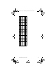
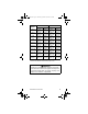


Table Of Contents
- General Information
- Installation
- Component Identification
- Maintenance
- Operation
- Blade Tower Brixing
- CEV Electronic Ice & Carbonation Control
- Flavor Magic Programming
- Flav’R-Pic External Programming
- Flav’R-Pic (FRP-250) Programming
- Flav’R-Pic (FRP-250) Brixing Procedure
- FlexTower Programming Modes
- Control Board Run or Dispense Mode
- The 6 Programming Modes on FlexTower Control Board
- To Access Programming Modes
- To Exit Programming Modes
- Manual Dispense Mode
- Timed Dispense Mode (Flavor Adder Dispensed)
- Water Calibration Mode
- Syrup Calibration Mode
- Touchpad Configuration Mode
- Touchpad LED Light Sequencing Mode (8 Selection Area Touchpad)
- Touchpad LED Light Sequencing Mode (4 Selection Area Touchpad)
- Adjustments
- Agitation Timer
- Troubleshooting
- Component Specifications
- Charts
- Diagrams
- Blade Tower Plumbing
- CEV-30i & CEV-30e Plumbing
- CEV-40i & CEV-40e Plumbing
- CT-6 Plumbing and Wiring
- CT-8 Plumbing and Wiring
- CF-1522 Plumbing
- DI-1522 Post-mix Plumbing
- DI-1522 Pre-mix Plumbing
- DI/DIL-2323 6 Valve Post-mix Plumbing
- DI/DIL-2323 8 Valve Post-mix Plumbing & Variety Valve
- DI/DIL-2323 10 Valve Post-mix Plumbing
- DI/DIL-2323 6 Valve Pre-mix Plumbing
- Flavor Magic Plumbing
- FRP-250 Plumbing Diagram
- FRP-250 & FRP-250SCI Tubing Layout
- FT-8 Plumbing
- FT-12 Plumbing
- FlexTower Water Recirculation Pump Flow
- FlexTower Water Chiller Flow
- MDH-302 12 Valve Plumbing
- MDH-402 16 Valve Plumbing
- MDH-402 20 Valve Plumbing
- S/SV150 6 Valve Diagram
- S/SV175 8 Valve Diagram
- S/SV200/250/SV-250QD 8 Valve Diagram
- S/SV200/250 10 Valve Diagram
- Flex Manifold Diagrams
- CEV Wiring
- CF Drop-In Series Wiring
- Drop-in Wiring
- Flavor Magic Wiring
- Flav’R-Pic (FRP-250) Wiring
- FlexTower Wiring
- MDH-302 & MDH-402 Wiring
- NGF-250 Wiring
- quickdraw Wiring
- S/SV/SVi Wiring
- Selectable Ice Wiring

Part Number STH14 9/10 29
FLEXTOWER FOOTPRINT
NOTE: The FlexTower must be secured to the
countertop using the four holes provided in the base of
the unit and using the hardware provided. Follow
customer guidelines for placement of the unit or
approximately 10 inches (25.4 cm) from the edge of
the counter. A mounting template is provided which is
printed on the shipping carton. NOTE: DO NOT
DISCARD SHIPPING CARTON UNTIL MOUNTING
TEMPLATE IS REMOVED.
ABCD
(2X) 3.407"
(8.65 cm)
(2X) 5.75"
(14.61 cm)
(2X) 11.265"
(28.61 cm)
(2X) 5.265"
(13.37 cm)
EFG
(4X) Ø 0.25"
(0.64 cm)
7.701"
(19.56 cm)
13.627"
(34.61 cm)
AB
C
D
E
F
G
Supply Line Opening
Through Bottom
Front of Unit
(Drainpan)
STH14.book Page 29 Thursday, September 23, 2010 3:35 PM