
Installation Guide
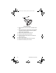
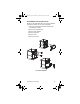
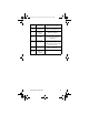


Table Of Contents
- General Information
- Installation
- Component Identification
- Maintenance
- Operation
- Blade Tower Brixing
- CEV Electronic Ice & Carbonation Control
- Flavor Magic Programming
- Flav’R-Pic External Programming
- Flav’R-Pic (FRP-250) Programming
- Flav’R-Pic (FRP-250) Brixing Procedure
- FlexTower Programming Modes
- Control Board Run or Dispense Mode
- The 6 Programming Modes on FlexTower Control Board
- To Access Programming Modes
- To Exit Programming Modes
- Manual Dispense Mode
- Timed Dispense Mode (Flavor Adder Dispensed)
- Water Calibration Mode
- Syrup Calibration Mode
- Touchpad Configuration Mode
- Touchpad LED Light Sequencing Mode (8 Selection Area Touchpad)
- Touchpad LED Light Sequencing Mode (4 Selection Area Touchpad)
- Adjustments
- Agitation Timer
- Troubleshooting
- Component Specifications
- Charts
- Diagrams
- Blade Tower Plumbing
- CEV-30i & CEV-30e Plumbing
- CEV-40i & CEV-40e Plumbing
- CT-6 Plumbing and Wiring
- CT-8 Plumbing and Wiring
- CF-1522 Plumbing
- DI-1522 Post-mix Plumbing
- DI-1522 Pre-mix Plumbing
- DI/DIL-2323 6 Valve Post-mix Plumbing
- DI/DIL-2323 8 Valve Post-mix Plumbing & Variety Valve
- DI/DIL-2323 10 Valve Post-mix Plumbing
- DI/DIL-2323 6 Valve Pre-mix Plumbing
- Flavor Magic Plumbing
- FRP-250 Plumbing Diagram
- FRP-250 & FRP-250SCI Tubing Layout
- FT-8 Plumbing
- FT-12 Plumbing
- FlexTower Water Recirculation Pump Flow
- FlexTower Water Chiller Flow
- MDH-302 12 Valve Plumbing
- MDH-402 16 Valve Plumbing
- MDH-402 20 Valve Plumbing
- S/SV150 6 Valve Diagram
- S/SV175 8 Valve Diagram
- S/SV200/250/SV-250QD 8 Valve Diagram
- S/SV200/250 10 Valve Diagram
- Flex Manifold Diagrams
- CEV Wiring
- CF Drop-In Series Wiring
- Drop-in Wiring
- Flavor Magic Wiring
- Flav’R-Pic (FRP-250) Wiring
- FlexTower Wiring
- MDH-302 & MDH-402 Wiring
- NGF-250 Wiring
- quickdraw Wiring
- S/SV/SVi Wiring
- Selectable Ice Wiring

Part Number STH14 9/10 67
FLEXTOWER DAILY CLEANING
Cleaning the grid, splash shield and drain pan:
1. Turn off the on/off rocker switch located on left
side of the unit.
2. Lift the grid and splash shield to remove them
from the drain pan.
3. Using mild soap, warm water and a clean cloth,
wipe the drain pan. Then, rinse with clean, warm
water. Allow plenty of warm (not hot) water to run
down the drain of the drain pan, to remove syrup
residue that can clog the drain opening.
4. Wash the grid and splash shield, then rinse with
clean water. Place the grid and splash shield back
in the drain pan.
5. Wash all exterior surfaces of the unit with warm
water and a clean cloth. Wipe again with a clean,
dry cloth.
Switch
Splash
Shield
STH14.book Page 67 Thursday, September 23, 2010 3:35 PM