
Installation Guide
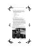
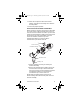
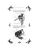
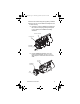
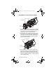
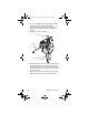
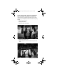
Table Of Contents
- General Information
- Installation
- Component Identification
- Maintenance
- Operation
- Blade Tower Brixing
- CEV Electronic Ice & Carbonation Control
- Flavor Magic Programming
- Flav’R-Pic External Programming
- Flav’R-Pic (FRP-250) Programming
- Flav’R-Pic (FRP-250) Brixing Procedure
- FlexTower Programming Modes
- Control Board Run or Dispense Mode
- The 6 Programming Modes on FlexTower Control Board
- To Access Programming Modes
- To Exit Programming Modes
- Manual Dispense Mode
- Timed Dispense Mode (Flavor Adder Dispensed)
- Water Calibration Mode
- Syrup Calibration Mode
- Touchpad Configuration Mode
- Touchpad LED Light Sequencing Mode (8 Selection Area Touchpad)
- Touchpad LED Light Sequencing Mode (4 Selection Area Touchpad)
- Adjustments
- Agitation Timer
- Troubleshooting
- Component Specifications
- Charts
- Diagrams
- Blade Tower Plumbing
- CEV-30i & CEV-30e Plumbing
- CEV-40i & CEV-40e Plumbing
- CT-6 Plumbing and Wiring
- CT-8 Plumbing and Wiring
- CF-1522 Plumbing
- DI-1522 Post-mix Plumbing
- DI-1522 Pre-mix Plumbing
- DI/DIL-2323 6 Valve Post-mix Plumbing
- DI/DIL-2323 8 Valve Post-mix Plumbing & Variety Valve
- DI/DIL-2323 10 Valve Post-mix Plumbing
- DI/DIL-2323 6 Valve Pre-mix Plumbing
- Flavor Magic Plumbing
- FRP-250 Plumbing Diagram
- FRP-250 & FRP-250SCI Tubing Layout
- FT-8 Plumbing
- FT-12 Plumbing
- FlexTower Water Recirculation Pump Flow
- FlexTower Water Chiller Flow
- MDH-302 12 Valve Plumbing
- MDH-402 16 Valve Plumbing
- MDH-402 20 Valve Plumbing
- S/SV150 6 Valve Diagram
- S/SV175 8 Valve Diagram
- S/SV200/250/SV-250QD 8 Valve Diagram
- S/SV200/250 10 Valve Diagram
- Flex Manifold Diagrams
- CEV Wiring
- CF Drop-In Series Wiring
- Drop-in Wiring
- Flavor Magic Wiring
- Flav’R-Pic (FRP-250) Wiring
- FlexTower Wiring
- MDH-302 & MDH-402 Wiring
- NGF-250 Wiring
- quickdraw Wiring
- S/SV/SVi Wiring
- Selectable Ice Wiring

72 Part Number STH14 9/10
6. Mix a solution of mild detergent to clean the
Quickdraw components. Using the detergent
solution and a soft bristle brush or clean cloth,
clean the following components:
- Ice wheel
-Cup locator
- Quickdraw chamber
-Door
- Ice chute cover
7. Rinse all parts in clean running water.
8. Mix a sanitizing solution of 1/4 ounce (7.4 ml)
liquid, unscented bleach (5.25% CL NaO
concentration) for each gallon of water. The
mixture must provide 100 PPM available chlorine.
9. Using the sanitizing solution, a soft bristle brush,
or a clean cloth, sanitize the components listed in
Step 6. The ice chamber must be sanitized with a
soft bristle brush to adequately clean the metering
wheel slot and drainage area.
10. Reverse the procedure to reassemble the
Quickdraw mechanism.
NOTE: When inserting the pin through the ice wheel,
you will have to align the pin with the pattern of the
wheel hole.
STH14.book Page 72 Thursday, September 23, 2010 3:35 PM