S, SV, SVi, NGF, & Quickdraw™ Beverage/Ice Dispensers Installation, Operation and Maintenance Manual Original Instructions — This manual is updated as new information and models are released. Visit our website for the latest manual. www.manitowocbeverage.
Safety Notices Read These Before Proceeding As you work on Manitowoc equipment, be sure to pay close attention to the safety notices in this manual. Disregarding the notices may lead to serious injury and/or damage to the equipment. nWarning PERSONAL INJURY POTENTIAL Throughout this manual, you will see the following types of safety notices: Do not operate equipment that has been misused, abused, neglected, damaged, or altered/modified from that of original manufactured specifications.
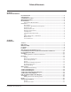
Table of Contents Section 1 General Information Read This Manual................................................................................................................ 5 Unit Inspection.................................................................................................................... 5 Serial Number Location...................................................................................................... 5 Warranty Information...................................................
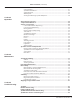
Table of Contents (continued) Unit Installation..................................................................................................................................... 21 Quickdraw Installations..................................................................................................................... 22 Setting Pressures.................................................................................................................................. 22 ADA Key Pads ....................
Section 1 General Information Read This Manual Warranty Information Manitowoc Beverage Equipment (MBE) developed this manual as a reference guide for the owner/operator and installer of this equipment. Please read this manual before installation or operation of the machine. A qualified service technician must perform installation and start-up of this equipment, consult Section 5 within this manual for service assistance. Visit www.manitowocbeverage.
General Information Accessories VARIETY VALVES Variety Valves are a great way of extending your beverage offerings with non-carbonated drinks without extending the dispenser footprint! The McCann’s Variety Valve is available in Autofill, Self-Serve, Sanitary Lever and Portion Control.
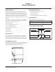
Section 2 Installation General Importan These instructions are provided to assist the qualified installer. Contact your Manitowoc Beverage Equipment Service Agent or call Manitowoc Beverage Equipment for information regarding start-up services. Failure to follow these installation guidelines may affect warranty coverage. The unit should be installed and serviced by a suitably trained person. Dimensions A H C D B Model/Ice Capacity A B C D S/SV-150 34.81" (88.4 cm) 23.00" (58.4 cm) 9.
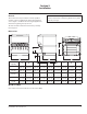
Installation Section 2 Footprints A C Minimum Area for Cutout D B Maximum Area for Cutout NOTE: Footprint for S/SV-175 shown. S & SV Maximum Minimum A B C D 150 19.00" (48.3 cm) 17.81" (45.2 cm) 8.00" (20.3 cm) 8.00" (20.3 cm) 175 21.00" (53.3 cm) 17.81" (45.2 cm) 8.00" (20.3 cm) 8.00" (20.3 cm) 200 26.00" (66.0 cm) 17.81" (45.2 cm) 8.00" (20.3 cm) 8.00" (20.3 cm) 250* 26.00" (66.0 cm) 17.81" (45.2 cm) 8.00" (20.3 cm) 8.00" (20.3 cm) 250QD* 26.00" (66.0 cm) 17.81" (45.
Section 2 Installation nWarning nWarning Cutting the countertop may decrease its strength. Counter must be braced to support the dispenser countertop weight plus ice storage capacity and weight of ice machine, if applicable. Carbon Dioxide (CO2) ALWAYS • • • • Location NEVER The location selected for the beverage dispenser must meet the following criteria. If any of these criteria are not met, select another location.
Installation Location Requirements for Top Mounted Ice Machine Installations Location — Avoid placing the dispenser and/or ice machine near heat sources such as radiators, ovens, refrigeration equipment and direct sunlight. Clearances — Refer to the ice machine installation manual for clearances. Front of ice machine to be flush with front of dispenser — Some ice machines may overhang at the back of the dispenser.
Section 2 Installation Assembly Q Series Baffle 1. Position baffle on top of water well with tab on the front and the other tab inside the water well. INSTALLING BAFFLE FOR ICE MACHINE INSTALLATIONS S Series Baffle 2. Mount the baffle on the left side of the ice machine using the hole and screw provided. 1. Remove both front panels. 2. Examine the ice machine to see if the machine has four screws on the lower front plastic panels. 3.
Installation Section 2 Electrical GENERAL nWarning All wiring must conform to local, state and national codes. Changes to the mains cable and plug can only be made by a qualified electrician. MINIMUM CIRCUIT AMPACITY The minimum circuit ampacity is used to help select the wire size of the electrical supply. (Minimum circuit ampacity is not the beverage/ice machine’s running amp load.) The wire size (or gauge) is also dependent upon location, materials used, length of run, etc.
Section 2 Installation nWarning When using electric appliances, basic precautions must always be followed, including the following: a. Read all the instructions before using the appliance. b. To reduce the risk of injury, close supervision is necessary when an appliance is used near children. c. Do not contact moving parts. d. Only use attachments recommended or sold by the manufacturer. e. Do not use outdoors. f.
Installation Section 2 Water Supply Importan RECOMMENDED PLUMBING All plumbing must conform to local, state, and national codes. Manitowoc recommends that a double non-return valve is fitted before the unit on installation. The unit is not connected to the water mains by a factory supplied hose set and it is up to the installer to fit an appropriate food grade hose, rated to a minimum operating pressure of 145 psi (10 bar, 1000000 Pa).
Section 2 Installation S/SV150 6 Valve Diagram Plumbing: 2-1-1-2 Manifolding *OPTIONAL* VARIETY VALVE ON #3 INTERNAL CARBONATOR TANK 1 – WATER (THRU COLDPLATE) VALVES “SYRUP LINES NOT SHOWN” CO2 6 5 2 4 1 3 3 4 2 2 – SYRUP (AMBIENT) 1 3 – SYRUP (AMBIENT) VALVES CARBONATOR OUT TO POST-CHILL PRE-CHILL OUT TO CARBONATOR CIRCUITS 1, 2 3 4 5, 6 2 1 1 2 4 – SYRUP (THRU COLDPLATE) Manifold: Change to carbonated or non-carbonated water. 1.
Installation Section 2 S/SV175 8 Valve Diagram Plumbing: 3-1-1-1-2 Manifolding *OPTIONAL* VARIETY VALVE ON #4 INTERNAL CARBONATOR TANK (OPTIONAL) 1 – WATER (THRU COLDPLATE) VALVES “SYRUP LINES NOT SHOWN” CO2 8 7 CARBONATOR OUT TO POST-CHILL PRE-CHILL OUT TO CARBONATOR VALVES CIRCUITS 6 5 2 1 1 4 2 – SYRUP (AMBIENT) 3 3 4 2 1 3 – SYRUP (AMBIENT) 7, 8 6 5 4 1, 2, 3 2 1 1 1 3 4 – SYRUP (THRU COLDPLATE) Manifold: Change to carbonated or non-carbonated water. 1.
Section 2 Installation S/SV200/250/SV-250QD 8 Valve Diagram Plumbing: 3-1-1-1-2 Manifolding *OPTIONAL* VARIETY VALVE ON #4 NOTE: SYRUP LINES NOT SHOWN VALVES 8 7 6 5 2 3 4 1 3 2 1 4 1 – WATER (THRU COLDPLATE) 2 – SYRUP (AMBIENT) 3 – SYRUP (AMBIENT) 1, 2, 3 VALVES CIRCUITS 3 4 1 5 6 7, 8 1 1 2 4 – SYRUP (THRU COLDPLATE) CARBONATOR OUT TO POST-CHILL CO2 PRE-CHILL OUT TO CARBONATOR Manifold: Change to carbonated or non-carbonated water. 1.
Installation Section 2 S/SV200/250 10 Valve Diagram Plumbing: 3-1-1-1-3 Manifolding NOTE: SYRUP LINES NOT SHOWN VALVES 10 9 CARBONATOR OUT TO POST-CHILL CO2 PRE-CHILL OUT TO CARBONATOR 8 7 6 5 4 3 2 VALVES 1, 2, 3 4 5, 6 7 8, 9, 10 CIRCUITS 3 1 2 1 3 1 Manifold: Change to carbonated or non-carbonated water. 1. Rotate plunger 180° using a 5/32" Hex Key wrench 2. Pull plunger up to get non-carbonated water. 3. Push plunger down to get carbonated water. 4.
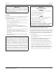
Section 2 Installation NGF-250 & NGF-250QD 8 Valve Diagram W/2 VARIETY VLVS VALVES STANDARD NO VARIETY VLV PLAIN WATER TO CARBONATOR PLAIN WATER SYRUP #1 SYRUP #2 SYRUP #4 SYRUP #3 SYRUP #6 SYRUP #5 SYRUP #8 SYRUP #7 SYRUP #9 SYRUP #11 SYRUP #10 SYRUP #12 VALVES VARIETY VALVE KEY PAD VARIETY VALVE BLOCK W-WATER W/2 VARIETY VLVS 3-FLAVOR 2-FLAVOR VALVES CIRCUITS 1-FLAVOR MANIFOLD TO CHANGE TO CARBONATED OR NON-CARBONATED WATER 1) ROTATE PLUNGER 180 USING A 5/32” ALLEN WRENCH 2) PULL P
Installation Section 2 CO2 Supply ROUTING INTERNAL CARB TANK PURGE TUBE Some models are equipped with an internal carbonation tank. These models require that the purge/pressure relief tubing be routed to a drain. Rear of Unit 1. Remove the splash panel. 2. Uncoil tubing and route between the front of the dispenser and the drain pan. To Drain 4. Verify the tubing is not kinked and then secure tubing to maintain a minimum 1" (2.5 cm) air gap at the drain. Follow any applicable local or national codes.
Section 2 Installation Step by Step Installation GENERAL S/SV/SVI/NGF Series dispensers have a stainless steel cabinet and lighted merchandiser standard. Beverage valves, coldplate connections, drain connections and electrical components are front serviceable. SPECIFICATIONS CHART Min. Max Water pressure (Incoming from Water Main) 40 psi (2.76 BAR 275,790 Pa) 55 psi (3.79 BAR 379,211 Pa) Ambient temperature 40°F (4°C) 105°F (41°C) 40 psi (2.76 BAR 275,790 Pa) 50 psi (3.
Installation Section 2 D. Mount the collector box to the bracket by sliding the right and left bracket tabs into the slots on the collector box. Right Bracket Tab Right Slot Left Bracket Tab Be sure the 90° rubber ice bin drain elbows are routed into the collector box. 90° Elbow 90° Elbow Left Tab In Slot Right Tab In Slot F. Reinstall the extended splash panel. 5. Fill bin with ice. 6. Set flexible manifold Carb/Non-Carb drinks for correct drink settings (see Recommended Plumbing on page 14). 7.
Section 2 Installation Importan If incoming water pressure is under 40 psi (2.76 BAR, 275,790 Pa), a water booster is recommended. If incoming water pressure is over 55 psi (3.79 BAR 379, 211 Pa), a water regulating valve is required. ADA KEY PADS These instructions are for installations with this option. 7. Connect the ADA ribbon cable to the ADA wire harness located to the left of the ice chute and held to the foam front by a wire clip. ADA Box Ribbon Cable ADA Harness ADA Wire Harness Clip 1.
Installation Section 2 11. Apply corresponding drink labels to the ADA key pads. Finish Installation NOTE: Drinks correspond from left to right on the left side of the unit, and right to left on the right side of the unit. If buttons are not used they will be blanked out. The Cubed/ Crushed buttons are only utilized on units configured with the Selectable Ice feature. (See ADA Key Pad Matrix.) 12. Put the splash panel and merchandiser back onto the unit and reinstall the screws that hold them in place.
Section 3 Operation General System Overview Dispenser Carbonator Tank Carbonate, Non-carbonate Beverage Manifold Countertop Syrup Tap Water Tap Water 1800 BIB Syrup Pump Bag-in-box Syrup Carton 75 CO2 60 CO2 CO2 CO2 Cylinder Typical Internal Carbonation Beverage Dispensing System Dispenser w/ Cold plate Countertop Non-carbonated Water Tap Water Syrup Syrup Carbonated Water CO2 Tap Water Carbonator Tank BIB Syrup Pump CO2 Cylinder 1800 Bag-in-box Syrup Carton 90105 60 CO2 CO2 Syrup
Operation Section 3 Component Identification Merchandiser Soda Valves Key Switch Carb/Non-Carb Water Manifold and Syrup/Soda Inlet (Behind Splash Panel) Drainpan Grid Splash Panel Counter Drainpan Sequence of Operation ICE RECOMMENDED FOR DISPENSING Dispensers are designed to dispense hard, cube ice up to one-inch square. The ice shapes and sizes listed below are recommended for dispensing.
Section 3 CARBONATION The purpose of the carbonator is to take regular tap water at street water pressure (minimum 20 psi, maximum 80 psi, dynamic or flowing pressure) 1/2" water line and increase the water to beverage system pressure (usually 100 psi). This water is then combined with the CO2 gas. Because the water and gas are at the same pressure, the CO2 will dissolve into the water. Chilling the mixture before dispensing will assist in locking the carbon dioxide into the water.
Operation 8. Lowered outgoing pressure – Set for 75 psi. Gauge indicates lowered outgoing pressure from the CO2 cylinder after being routed through the primary pressure regulator at 100 psi. Section 3 FIGAL SYSTEM Figal refers to the stainless steel tanks of pre-mix beverage or post-mix syrup. A small CO2 tank pushes the beverage out of the Figal tank. 9. Secondary pressure regulator – Lowers the CO2 gas pressure before the CO2 gas flows to the syrup pump. CO2 pressure activates the syrup pump. 10.
Section 3 Operation When this jumper is in place, the LED will blink at onesecond intervals. This is the run mode. When the jumper is open, the LED will flash every 0.4 second. This is the test mode and the timer will cycle every 55 seconds in test mode. If the timer is left in test mode, it will automatically reset to run mode. Begin by observing the chute by slowly pushing against the rocking chute.
Operation Section 3 Largest Size / Increase Button Ice Dispense Mode Switch Ice Dispense Power Switch Auto Manual Smallest Size / Decrease Button Manual Push for Ice Switch QUICKDRAW ICE PORTION ADJUSTMENTS The Quickdraw ice dispensing system has adjustable ice portion sizes. Follow the directions below to set the ice portion size. Each portion size must be checked according to customer specification at the time of installation. 1.
Section 3 Operation SENSOR BEAM Rectangular Window in Ice Chamber Emitter Receiver Beam 3. Tighten screws on left and right side of assembly. Sensor Beam Sequence of Operation 4. Test the Quickdraw. 1. Ice fills the ice chute until it interrupts the beam. 2. Paddlewheel stops. 3. Ready for the next portioned dispense. Adjustment 1. Loosen screws on left & right side of assembly. Left Adjustment Screw 2. Adjust sensor board sensor eyes to the center of the rectangular window on ice chamber.
Operation BRIX CHECK Step 1 - Gather Tools Section 3 Step 4 - Fill Brix Cup Tools you will need; brix cup and S tube. Syrup Ratio NOTE: Follow instructions on 2a or 2b depending on Valve Type that is being checked. 6:1 5:1 WATER 5.5:1 Step 2a - Attaching S Tube To Multi-flavor Valve 8.5:1 10 9 8 7 Syrup Water 6 5.5 to 1 5 4 8.5 to 1 3 2 OZ. High-Yield Brix Cup • Remove nozzle and syrup diffuser from valve. • Slide white end of S Tube over tip of diffuser snuggly.
Section 4 Maintenance Cleaning & Sanitizing GENERAL You are responsible for maintaining the dispenser in accordance with the instructions in this manual. Maintenance procedures are not covered by the warranty. Clean and sanitize the dispenser every six months for efficient operation. An extremely dirty dispenser may require more frequent cleaning and sanitizing due to operating environment and/or water quality.
Maintenance Section 4 Cleaning/Sanitizing Procedure 6. Prepare approximately 2 gallons (7.6 liters) of sanitizing solution by mixing 1/2 ounce (15 ml) of household bleach (that contains 5.25% sodium hypochlorite) with 2 gallons (7.6 liters) of 120°F water. The mixture must not exceed 100 PPM of chlorine. Or mix a solution of any approved sanitizer, following the directions for mixing and applying the sanitizer. This procedure must be performed a minimum of once every six months.
Section 4 Preventative Maintenance Preventative maintenance is a vital part of keeping your dispenser in top condition. Following the guidelines below will assist you in continued trouble-free operation of your unit. 1. Conduct daily maintenance of the machine. Maintenance C D E F 2. Perform monthly maintenance of the machine. 3. Perform periodic maintenance and sanitizing of beverage system. 4. Do not overfill the dispenser bin with ice. G 5.
Maintenance Section 4 7. Remove agitator arm and paddlewheel pin. Non-front Serviceable Motor a. Rotate the agitator arm so the paddle wheel pin handle is pointing up, toward the ceiling. b. Prepare agitator pin for removal by removing the stainless steel split ring. c. Then remove the paddle wheel pin from the hole in the agitator. d. Push the agitator bar toward the back of the unit until the agitator is free of the paddle wheel hub. Front Serviceable Motor a.
Section 4 Maintenance QUICKDRAW COMPONENTS 1. Turn the beverage valve switch on the front left side to the off position. B. Push the bottom of chute to rear until it stops. C. Rock the top of the chute forward until top of chute clears unit. Ice Dispense Switch Beverage Valve Switch 2. Place a receptacle (bucket or large cup) under the ice dispense chute. 3. Place the ice dispense switch to MANUAL mode. The door will open and ice will fall into the bucket or cup. 4. Remove the ice chute cover: A.
Maintenance Section 4 8. Using the sanitizing solution, a soft bristle brush, or a clean cloth, sanitize the components listed in Step 5. The ice chamber must be sanitized with a soft bristle brush to adequately clean the drainage area. 4. Remove the agitator assembly from the dispenser bin by pushing the agitator to the back of the bin. Angle the front of the agitator to the side. Pull the agitator forward then out of the dispenser. 9. Reverse the procedure to reassemble the Quickdraw mechanism. 5.
Section 4 FRONT SERVICEABLE GEAR MOTOR REMOVAL These instructions are provided as a guide for the removal of the gear motor. Depending on the model number of your dispenser, these instructions may vary slightly. 1. Unplug the dispenser. 2. Unplug the motor. 3. Remove motor mount pins. Maintenance 6. New motor must have the same alignment (within 15 degrees). 7. To get correct alignment you can do one of two things: a. Turn drive shaft with an adjustable wrench, being careful not to damage the drive shaft.
Maintenance Section 4 Sanitizing 2. Disconnect the “syrup-line side” of the BIB connector. BEVERAGE SYSTEM CLEANING nWarning Flush sanitizing solution from syrup system. Residual sanitizing solution left in system could create a health hazard. nWarning When using cleaning fluids or chemicals, rubber gloves and eye protection must be worn. 3. Rinse connector with warm tap water. Sanitize the beverage system at initial start-up as well as regularly scheduled cleaning.
Section 4 5. Draw rinse water through system until clean water is dispensed. Most beverage valves allow the syrup side to be manually activated by depressing the syrup pallet. 6. Connect Bucket 2 to system. 7. Draw detergent solution through system until solution is dispensed. 8. Repeat steps 2-7 until all syrup circuits contain detergent solution. 9. Allow detergent solution to remain in the system for 5 minutes. 10. Connect Bucket 3 to system. 11.
Maintenance Section 4 THIS PAGE INTENTIONALLY LEFT BLANK 42 Part Number 020003996 3/15
Section 5 Troubleshooting Checklist If a problem arises during operation of your dispenser, follow the checklist below before calling service. Routine adjustments and maintenance procedures are not covered by the warranty. Problem Dispenser will not dispense ice (and NO SOUNDS are heard when machine is activated). Possible Cause To Correct No power. Check electrical connection. Loose wire in electrical system. Thoroughly check all wire connections. Dispenser overloaded with ice.
Troubleshooting Section 5 Drink Troubleshooting Condition Water only dispensing Syrup and CO2 only dispensing Investigation No pressure Carbonator Check Correction Regulator(s) out of adjustment Check/adjust regulator(s). Out of CO2 Install fresh tank. Defective regulator(s) Check/repair/replace regulator(s). CO2 line pinched, kinked or obstructed Check/repair/replace CO2 line. No power Check power supply. Plug in carbonator or reset breaker. Water supply Make sure water is turned “on”.
Section 5 Troubleshooting Condition No water, syrup or gas dispensing Investigation Check Is there power to the unit? No power Correction Plug in unit or reset breaker. Power to control box Replace fuse or control box. Is power coming through the key switch? Key switch “off” Turn switch “on”. Key switch defective Replace key switch. Is there power to the key switch? No power through the transformer Reset/replace transformer.
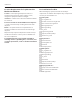
Troubleshooting Section 5 Quickdraw Ice Portion Control Program YES SWITCH IN AUTO MODE SUPPLY POWER ON POWER UP DISPLAYS “8888” THEN “____” DISPENSE CHUTE FILLED W/ ICE NO PRESS ANY SIZE BUTTON TO DISPENSE PROGRAMMED SIZE AUTO MODE NO AUGER TIMES OUT IN 30 SEC IF CHUTE CANNOT BE FILLED W/ICE DISPLAY SHOWS “_ICE” INDICATING OUT OF ICE TO MANUALLY DISPENSE PRESS AND HOLD “MANUAL PUSH FOR ICE” SWITCH SWITCH IN MANUAL MODE YES FIXED MAXIMUM TIME IS 6 SEC IF PROGRAMMED PULSE COUNT IS NOT REACHE
SERVEND 2100 FUTURE, SELLERSBURG, IN 47172 800-367-4233 WWW.MANITOWOCBEVERAGE.COM/US Every new piece of Manitowoc Foodservice equipment comes with KitchenCare™ and you choose the level of service that meets your operational needs from one restaurant to multiple locations.