
Installation Guide


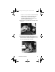
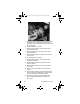


Table Of Contents
- General Information
- Installation
- Component Identification
- Maintenance
- Operation
- Blade Tower Brixing
- CEV Electronic Ice & Carbonation Control
- Flavor Magic Programming
- Flav’R-Pic External Programming
- Flav’R-Pic (FRP-250) Programming
- Flav’R-Pic (FRP-250) Brixing Procedure
- FlexTower Programming Modes
- Control Board Run or Dispense Mode
- The 6 Programming Modes on FlexTower Control Board
- To Access Programming Modes
- To Exit Programming Modes
- Manual Dispense Mode
- Timed Dispense Mode (Flavor Adder Dispensed)
- Water Calibration Mode
- Syrup Calibration Mode
- Touchpad Configuration Mode
- Touchpad LED Light Sequencing Mode (8 Selection Area Touchpad)
- Touchpad LED Light Sequencing Mode (4 Selection Area Touchpad)
- Adjustments
- Agitation Timer
- Troubleshooting
- Component Specifications
- Charts
- Diagrams
- Blade Tower Plumbing
- CEV-30i & CEV-30e Plumbing
- CEV-40i & CEV-40e Plumbing
- CT-6 Plumbing and Wiring
- CT-8 Plumbing and Wiring
- CF-1522 Plumbing
- DI-1522 Post-mix Plumbing
- DI-1522 Pre-mix Plumbing
- DI/DIL-2323 6 Valve Post-mix Plumbing
- DI/DIL-2323 8 Valve Post-mix Plumbing & Variety Valve
- DI/DIL-2323 10 Valve Post-mix Plumbing
- DI/DIL-2323 6 Valve Pre-mix Plumbing
- Flavor Magic Plumbing
- FRP-250 Plumbing Diagram
- FRP-250 & FRP-250SCI Tubing Layout
- FT-8 Plumbing
- FT-12 Plumbing
- FlexTower Water Recirculation Pump Flow
- FlexTower Water Chiller Flow
- MDH-302 12 Valve Plumbing
- MDH-402 16 Valve Plumbing
- MDH-402 20 Valve Plumbing
- S/SV150 6 Valve Diagram
- S/SV175 8 Valve Diagram
- S/SV200/250/SV-250QD 8 Valve Diagram
- S/SV200/250 10 Valve Diagram
- Flex Manifold Diagrams
- CEV Wiring
- CF Drop-In Series Wiring
- Drop-in Wiring
- Flavor Magic Wiring
- Flav’R-Pic (FRP-250) Wiring
- FlexTower Wiring
- MDH-302 & MDH-402 Wiring
- NGF-250 Wiring
- quickdraw Wiring
- S/SV/SVi Wiring
- Selectable Ice Wiring

90 Part Number STH14 9/10
CEV Electronic Ice & Carbonation Control
Element Function
Voltage Selection Switch
(Red Side Switch)
• Switch is used to select voltage,
115 Volt or 230 Volt option.
• When switch is in 115 Volt
position the operating voltages
are 100 Volts 50 Hertz and 120
Volts 60 Hertz.
• When switch is in 230 Volt
position the operating voltages
are 220-240 Volts 50 Hertz and
208-230 Volts 60 Hertz.
On-Off Switch • Switch supplies power to all
control functions.
• When switch is in “on” position
the agitation motor, transformer,
merchandiser bulb and green
power LED will be energized.
(The green power LED will flash
once per second for 5 seconds
then stay on continuously.)
Default Modes – LED/
Default (RED)
• RED Carbonator LED =
Default
• RED Compressor LED =
Default
• If the carbonator motor run time
exceeds the preset fill times,
which are (3) minutes or (7)
minutes. The default mode will
shut power off to carbonator
pump motor for (15) minutes. It
will then activate for one minute
and if the motor does not shut
down within the one-minute time
frame the (15) minute off time and
(1) minute on time default mode
will repeat. The process will occur
a total of (4) times and then the
unit will shut down, requiring
service or a manual reset.
Disconnecting the power supply
from unit or positioning
carbonator switch to the “off”
position and then returning switch
to “on” position will reset control
to normal operation (only applies
to Internal Carb. units)
• If the ice bank probe does not
detect water in the CEV tub, the
refrigeration will shut down and
the compressor LED turns RED.
= 115 Volt Position
= 230 Volt Position
STH14.book Page 90 Thursday, September 23, 2010 3:35 PM