Indigo Ice Machines Installation, Operation and Maintenance Manual This manual is updated as new information and models are released. Visit our website for the latest manual.
Safety Notices Safety Notices Read these precautions to prevent personal injury: • • • • • nWarning Follow these precautions to prevent personal injury during installation of this equipment: Read this manual thoroughly before operating, installing or performing maintenance on the equipment. Failure to follow instructions in this manual can cause property damage, injury or death. Routine adjustments and maintenance procedures outlined in this manual are not covered by the warranty.
nWarning Follow these electrical requirements during installation of this equipment. • All field wiring must conform to all applicable codes of the authority having jurisdiction. It is the responsibility of the end user to provide the disconnect means to satisfy local codes. Refer to rating plate for proper voltage. • This appliance must be grounded. • This equipment must be positioned so that the plug is accessible unless other means for disconnection from the power supply (e.g.
Table of Contents Safety Notices Safety Notices.................................................................................................................... 3 Section 1 General Information Ice Deflector....................................................................................................................... 7 Bin Level Accessory Kit....................................................................................................... 7 Bin Installation..................................
Table of Contents (continued) Section 3 Operation Control Panel Features..................................................................................................... 27 Buttons........................................................................................................................... 27 Display Panel.................................................................................................................. 27 Overview of Menu Navigation..........................................
Section 1 General Information Ice Deflector Top Air Discharge Kit An ice deflector is required when the ice machine is installed on a bin. An ice deflector is not required when the ice machine is installed on a dispenser. The top air discharge kit can be used on select ice machine models. This kit directs warm exhaust air upward rather than out the side panels.
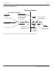
General Information Section 1 How To Read A Model Number Full Model Number Base Model Number ICE CUBE SIZE R - Regular D - Dice Y - Half-Dice Not Used On IB Models ICE MACHINE MODEL I - Indigo Model IB - Ice Beverage CONDENSER TYPE A - Self-Contained Air -Cooled W - Self-Contained Water -Cooled N - Remote Air-Cooled C - CVD Air-Cooled DC - IB Dice Model YC - IB Half Dice D - Factory Use Only P - Correctional Model M - Marine Model # HERTZ 5 - 50HZ 6 - 60HZ I Y 1000 W3 – 263PHPX X - LuminIce Ice Mac
Section 2 Installation Installation Minimum/Maximum Temperatures Model Location Requirements All Ice Machine Head Sections The location selected for the ice machine head section must meet the following criteria. If any of these criteria are not met, select another location. • The location must be indoors and must be free of airborne and other contaminants. • The location must not be near heat-generating equipment or in direct sunlight.
Installation Section 2 Clearance Requirements I0300 Top/Sides Back I0450/I0500/ I0600/ I0850/I0900/I1000/ I1100 Top/Sides Back I0320/I0520 Top/Sides Back I0500 230/50/1 Tropical Rating Top Sides/Back I1200 Top Sides Back I1400/I1800 Top/Sides Back I3300 Top/Sides Back QuietQube Model Clearance Requirements Self-Contained Air-Cooled 40 cm (16") 13 cm (5") Self-Contained Water‑Cooled 20 cm (8") 13 cm (5") Self-Contained Air-Cooled Water-Cooled or Remote Condenser 20 cm (8") 13 cm (5") 20 cm (8") 13 c
Section 2 Installation Bin Installation Air Baffle NOTE: When using casters, the units must be tethered or secured to comply with all applicable codes. Swivel casters must be mounted on the front and rigid casters must be mounted on the rear. Lock the front casters after installation is complete. Self-Contained Air-cooled Only 1. Remove threaded plug from drain fitting. 2. Screw the leveling legs onto the bottom of the bin. The air-cooled baffle prevents condenser air from recirculating.
Installation Section 2 Electrical Requirements Fuse/Circuit Breaker All electrical work, including wire routing and grounding, must conform to local, state and national electrical codes. The following precautions must be observed: A separate electrical disconnect, which disconnects all poles and has 3 mm (3/16") contact separation, must be provided for fixed wiring. Circuit breakers must be H.A.C.R. rated in USA. • The ice machine must be grounded.
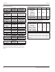
Section 2 Installation Maximum Breaker Size & Minimum Circuit Amperage Chart NOTE: Due to continuous product improvements, this information is for reference only. Please refer to the ice machine data plate to verify electrical data. Data plate information overrides information listed on this page.
Installation Section 2 QuietQube Head Sections Ice Machine Ice Beverage Models All Non IB QuietQube Models Voltage/Phase/Cycle 115/1/60 230/1/60 115/1/60 208-230/1/60 230/1/50 Maximum Fuse/Circuit Breaker 15 amp 15 amp 15 amp 15 amp 15 amp Minimum Circuit Amps N/A N/A 1.1 1.1 1.5 Total Amps 1.1 1.
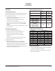
Section 2 Installation ICVD Interconnecting Wiring ICVD Transformer Wiring Indigo QuietQube ice machines require interconnecting low voltage wiring (included with Manitowoc line sets) to energize the contactor coil and verify the LPCO & HPCO are closed. This circuit also initiates a time delay whenever the LPCO or HPCO open. Failure to properly wire the ICVD condensing unit or ice machine head section will result in a non-operational machine.
Installation Section 2 Water Supply and Drain Line Sizing/Connections • Local water conditions may require treatment of the water to inhibit scale formation, filter sediment, and remove chlorine odor and taste. • Connect ice making water inlet to potable water only. • Do not connect to hot water supply. • Install a water shut-off valve. • Insulate water and drain lines to prevent condensation. ,Caution Do not apply heat to water inlet valve or water drain fittings.
Section 2 Installation Drain Connections Auxiliary Base Drain Installation Follow these guidelines when installing drain lines to prevent drain water from flowing back into the ice machine and storage bin: Two types of auxiliary drain are located in the ice machine base to remove moisture in high humidity areas: With or without a drain socket. • Drain lines must have a of run 2.5 cm per meter (1.5 inch drop per 5 feet) and must not create traps.
Installation Section 2 Remote Condenser and Remote Condensing Unit Refrigeration System Installation Each ice machine head section ships from the factory with a refrigerant charge appropriate for the entire system operation. The serial tag on the ice machine indicates the refrigerant charge. QuietQube Models QuietQube® Ice Machine I0680C IB690C IB0686C IB0696C I0870C IB0890C IB0890C I0976C I1070C IB1090C I1176C I1470C I1476C I1870C I2170C Remote Single Circuit Condenser ICVD0695 680 g - 1.
Section 2 Installation CALCULATING REMOTE CONDENSER & REMOTE CONDENSING UNIT INSTALLATION DISTANCES Line Set Length 1. Insert the measured rise into the formula below. Multiply by 1.7 to get the calculated rise. The maximum tubing length is 30 meters (100 feet). 2. Insert the measured drop into the formula below. Multiply by 6.6 to get the calculated drop. Line Set Rise/Drop The maximum rise is 10.7 meters (35 feet). 3. Insert the measured horizontal distance into the formula below.
Installation Section 2 ,Caution The refrigeration system warranty will not apply if the Manitowoc Ice Machine and Manitowoc ICVD Condensing Unit are not installed according to specifications. This warranty also will not apply if the refrigeration system is modified with a condenser, heat reclaim device, or other parts or assemblies not manufactured by Manitowoc. 10 METER (30 FEET) MAX. DISTANCE Step 1 Secure the Condenser.
Section 2 Installation QuietQube Models Only Step 3 Connect the Line Set. Remote Condensers Only In most cases, by routing the line set properly, shortening will not be necessary. When shortening or lengthening is required, do so before connecting the line set to the ice machine or the remote condenser. This prevents the loss of refrigerant in the ice machine or condenser. The quick connect fittings on the line sets are equipped with access valves.
Installation Section 2 Step 4 • • • A retention valve is present in the compressor discharge line. The retention valve requires evacuation connections at four points. Valve core removal tools that allow for removal and installation of the valve cores without removing hoses for the manifold gauge set are recommended to decrease the evacuation time. 1. Low side shut off valve on the back of the ice machine Ice Machine Head Section 2.
Section 2 Installation Step 5 Open Valves for the Line Set. You will not hear refrigerant flow when the valves are opened. Refrigerant will not flow until the ice machine is started and the solenoid valve opens. • All valve caps must be reinstalled, tightened and leakchecked to assure no refrigerant leakage exists.
Installation Step 6 Section 2 Connect Wiring to Condensing Unit or Remote Condenser and Ice Machine Head Section. ICVD REMOTE CONDENSING UNIT Attach wiring to terminal strip in control box of condensing unit and control board in ice machine head section. Match wire labels to connections see “ICVD Interconnecting Wiring” on page 15 and “ICVD Transformer Wiring” on page 15. REMOTE CONDENSER The remote condenser voltage matches the ice machine head section voltage see “Remote Condenser Wiring” on page 15.
Section 2 Installation Starting the Ice Machine 7. Use the Down arrow to highlight Time & Date. All Manitowoc ice machines are factory-operated and adjusted before shipment. Normally, new installations do not require any adjustment. 8. Press the Checkmark. The date will appear on the first line of the display (Mo/Day/Yr) and the time will appear on the second line (24 Hour). The month will be underlined.
Installation Section 2 Remove Ice Thickness Probe Shipping Brackets Ice Thickness Check Remove and discard shipping brackets before starting the ice machine. After a harvest cycle, inspect the ice cubes in the ice storage bin. The ice thickness probe is factory-set to maintain the ice bridge thickness at 3 mm (1/8"). Starting the Ice Machine Step 1 Refer to cleaning and sanitizing procedure and sanitize the ice machine and bin before placing in operation.
Section 3 Operation Power Button Cleaning Button Manitowoc Off On / Off Mode LCD Display [ ! ] } Menu Button Status Lines Alert/Message Line Checkmark Left Arrow Up and Down Arrows Control Panel Features The Indigo™ control panel offers a series of pressuresensitive buttons and a four-line, interactive display panel. BUTTONS Power Button: Powers the ice machine when in the On/ Off Mode. The ice machine can also be programmed to automatically power on and off in two Energy Saver modes.
Indigo™ Models Overview of Menu Navigation Menu Navigation Overview Operation Menu Button ON/OFF Button Section 3 Cleaning Button Timer Initiated Home Screen When Alert Present When Message Present Alerts Messages AuCS Clean Function Clean Function Main Menu Machine Info Energy Saver Set-up Password Entry (Optional) 90/70 Capacity Model Number Ice Machine Head Serial Number Condenser Serial Number Warranty Install Date Manufacture Date Main Software Version Display Software Version Exit L
Section 3 Operation Display Panel Navigation Alerts and Messages [Time & Date >]▼ Time Config > Units > ▼ Highlights: Brackets indicate if a line on the screen is “highlighted” or actionable. Move the brackets from line to line using the Down or Up arrow. Move the brackets down from the fourth line to view more of the menu displayed. Arrows: Two kinds of arrows give cues to additional information. “>” symbols show that another screen is available by pressing the Checkmark while a line is highlighted.
Operation Section 3 Main Menu From the Home screen, press the Menu button to enter the Main menu, where you can choose to see machine information, make setup changes, set the Energy Saver mode, or enter the Service Menu. To enter a four digit password of your choosing use the following procedure. 1. Press the Menu button. 2. From the Main menu, use the Down arrow to highlight Set-Up and press the Right arrow.
Section 3 Operation SET-UP MENU From the Main menu, use the Down arrow to navigate to SetUp and press the Checkmark. Select and customize machine settings on this menu. Press the Left arrow to return to previous screens. Set-Up Language Time & Date Language 1. From the Set-Up menu, use the Down arrow to highlight Language. 2. Press the Checkmark. You can choose to view the display in a language other than English by highlighting your choice and pressing the Checkmark.
Operation Section 3 Units LCD Brightness 1. From the Set-Up menu, use the Down arrow to highlight Units. Here, the brightness of the LCD display can be adjusted. 2. Press the Checkmark. On this screen, you can choose whether the ice machine will display measurements in Celsius or Fahrenheit, kilograms or pounds, and gallons or liters by highlighting your choice of each pair and pressing the Checkmark. Selecting one of each pair will deselect the other.
Section 3 Operation Clean Minder Air Filter Clean Minder is a feature that displays a cleaning reminder at a set time interval. The ice machine has a feature that displays a clean air filter reminder at a set time interval. 1. From the Set-Up menu, use the Down arrow to highlight Clean Minder. 1. From the Set-Up menu, use the Down arrow to highlight Air Filter. 2. Press the Checkmark.
Operation LuminIce® II Reminder The LuminIce® growth inhibitor recirculates the air in the ice machine foodzone over a UV bulb. This process will inhibit the growth of common micro-organisms on all exposed foodzone surfaces. The LuminIce® II has a feature that displays a reminder to change its bulb every 12 months. 1. From the Set-Up menu, use the Down arrow to highlight LUMINICE. Section 3 ENERGY SAVER MENU From the Main menu, use the Down arrow to navigate to Energy Saver and press the Checkmark.
Section 3 Operation Ice Bin Level Sensor Statistics Ice bin sensor is an optional accessory that allows the ice level in the bin to be set to one of three different levels. The bin level can be set seasonally to match usage, which results in lower energy costs and fresher ice. 1. From the Energy Saver menu, use the Down arrow to highlight Statistics. 1. In the Energy Saver menu, ensure that Ice Program is highlighted and press checkmark. 2. Press the Checkmark.
Operation Section 3 Service Menu Real Time Data From the Main menu, use the Down arrow to navigate to Service and press the Checkmark. This menu is intended for the use of trained service personnel. Press the Checkmark with RealTime Data highlighted to get readings on Time & Temp, Inputs and Outputs. Data History Press the Checkmark with Diagnostics highlighted to enter screens where you can run diagnostics on the control board, sensors and switches.
Section 3 Operation Ice Making Sequence of Operation Safety Limits Ice machines and storage bins produce and store ice for human consumption and product cooling. Safety limits are stored and indicated by the control board after three cycles. The number of cycles required to stop the ice machine varies for each safety limit. NOTE: The power button must be depressed and the water curtain/ice dampers must be in place on the evaporator before the ice machine will start.
Operation Section 3 Ice Thickness Check OPERATIONAL CHECKS General Manitowoc ice machines are factory-operated and adjusted before shipment. Normally, new installations do not require any adjustment. To ensure proper operation, always follow the Operational Checks: • when starting the ice machine for the first time • after a prolonged out of service period • after cleaning and sanitizing NOTE: Routine adjustments and maintenance procedures are not covered by the warranty.
Section 4 Maintenance Cleaning and Sanitizing Cleaning/Sanitizing Procedure General This procedure must be performed a minimum of once every six months. You are responsible for maintaining the ice machine in accordance with the instructions in this manual. Maintenance procedures are not covered by the warranty. Clean and sanitize the ice machine every six months for efficient operation.
Maintenance Section 4 Cleaning/Sanitizing Procedure ,Caution Use only Manitowoc approved Ice Machine Cleaner and Sanitizer for this application (Manitowoc Cleaner part number 94-0546-3 and Manitowoc Sanitizer part number 94-0565-3). It is a violation of Federal law to use these solutions in a manner inconsistent with their labeling. Read and understand all labels printed on bottles before use. CLEANING PROCEDURE ,Caution Do not mix Cleaner and Sanitizer solutions together.
Section 4 Maintenance Step 6 Mix a solution of cleaner and lukewarm water. Depending upon the amount of mineral buildup, a larger quantity of solution may be required. Use the ratio in the table below to mix enough solution to thoroughly clean all parts. Solution Type Cleaner Water 4 L (1 gal) Mixed With 475 ml (16 oz) cleaner Step 7 Use half of the cleaner/water mixture to clean all components.
Maintenance Section 4 Parts Removal for Cleaning/Sanitizing SINGLE EVAPORATOR ICE MACHINES A. Remove the water curtain • Gently flex the curtain in the center and remove it from the right side. • Slide the left pin out. B. Remove the ice thickness probe • Compress the hinge pin on the top of the ice thickness probe. • Pivot the ice thickness probe to disengage one pin then the other. The ice thickness probe can be cleaned at this point without complete removal.
Section 4 Maintenance MULTIPLE EVAPORATOR ICE MACHINES • After the wires are disconnected, remove the two thumbscrews and lift the water pump assembly out of the ice machine. • Remove the thumbscrews securing the water pumps (2 each pump) and remove water pumps. Do not immerse the water pump motor in cleaner or sanitizer solutions. • Remove the water level probe from the assembly housing. F. Remove the water trough • Pull forward on the water trough to remove. A.
Maintenance Section 4 Preventative Maintenance Cleaning Procedure Cleaning the Condenser Filter This procedure cleans all components in the water flow path, and is used to clean the ice machine between the bi-yearly cleaning/sanitizing procedure. The washable filter on self-contained ice machines is designed to catch dust, dirt, lint and grease. Clean the filter with a mild soap and water. Ice machine cleaner is used to remove lime scale and mineral deposits.
Section 5 Troubleshooting Before Calling for Service Checklist If a problem arises during operation of your ice machine, follow the checklist below before calling service. Routine adjustments and maintenance procedures are not covered by the warranty. Problem Ice machine does not operate. Possible Cause No electrical power to the ice machine and/or condensing unit. High pressure cutout tripping. Energy Saver or other field entered programming is stopping ice machine. Water curtain off or stuck open.
Troubleshooting Problem Ice machine produces shallow or incomplete cubes, or the ice fill pattern on the evaporator is incomplete. Section 5 Possible Cause Ice thickness probe is out of adjustment. Water trough level is too low. Water inlet valve filter screen is dirty. Water filtration is poor. Hot incoming water. Low ice capacity. Water inlet valve is not working. Incorrect incoming water pressure. Ice machine is not level. Water inlet valve filter screen is dirty. Incoming water supply is shut off.
MANITOWOC ICE 2110 SOUTH 26TH STREET, MANITOWOC, WI 54220 800-545-5720 WWW.MANITOWOCICE.COM WWW.WELBILT.COM Bringing innovation to the table Welbilt provides the world’s top chefs, and premier chain operators or growing independents with industry leading equipment and solutions. Our cutting-edge designs and lean manufacturing tactics are powered by deep knowledge, operator insights, and culinary expertise. All of our products are backed by KitchenCare® – our aftermarket, repair, and parts service.