
Owner's Manual


Part Number: 000013325 Rev 02 6/17 9
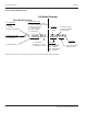
Installation
Location Requirements
The location selected for the ice machine head section must
meet the following criteria. If any of these criteria are not
met, select another location.
• The location must be indoors and must be free of
airborne and other contaminants.
• The location must not be near heat-generating
equipment or in direct sunlight.
• The location must allow enough clearance for water,
drain, and electrical connections in the rear of the ice
machine.
• The location must not obstruct airflow through or around
the ice machine.
Installation Requirements
• The ice machine and bin must be level.
• Vent the ice machine and bin drains separately.
• Bin drain termination must have an air gap.
• The ice machine and bin must be sanitized after
installation.
• The drain line must contain a union or other suitable
means of disconnection at the ice machine.
QuietQube Models Only
• The ice machine top panel can be trimmed with an
aviator snips to allow the line set, water line and
electrical connections to exit the top. Only cut out what is
needed, the back panel must support the top panel.
• The water inlet and electrical connection must contain a
service loop to allow future access.
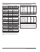
Minimum/Maximum Temperatures
Model
Minimum Air
Temperature
Maximum Air
Temperature
All Ice Machine Head Sections
2°C
35°F
43°C
110°F
All Remote Condensers
-29°C
-20°F
49°C
120°F
QuietQube Condensing Units
ICVD0695 - ICVD0696
ICVD1195 - ICVD1196
ICVD2095 - ICVD2196
-29°C
-20°F
49°C
120°F
ICVD0895 - ICVD0896
ICVD0996
ICVD1095 - ICVD1096
ICVD1495 - ICVD1496
ICVD1895 - ICVD1896
-29°C
-20°F
54°C
130°F
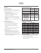
Ice Machine Heat of Rejection
Ice Machine Heat of Rejection
Series Air Conditioning Peak
I0300 4600 5450
I0320 3800 6000
I0450 5400 6300
I0500 6100 6900
I0520 5400 6300
I0600 9000 13900
I0850 13000 16000
I0906 13000 16000
I1000 16250 18600
I1200 20700 24500
I1400 23500 27000
I1800 31000 36000
I3300 45000 51000
Use this information when:
• Sizing air conditioning equipment where self-contained
air-cooled ice machines are installed.
• Determining the load on a cooling tower – Use the peak
figure for sizing the load.
Section 2
Installation