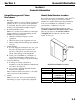
Q Model AuCS®A Accessory (Automatic Cleaning System) Installation Use and Care Manual This Manual Covers Installation, Use and Care Information for the AuCS® A Accessory. We reserve the right to make product improvements at any time. Specifications and design are subject to change without notice.
Safety Notices Procedural Notices When installing or using the AuCS®A accessory, be sure to pay close attention to the safety notices in this manual. Disregarding the notices may lead to serious injury and/or damage to the ice machine or AuCS® accessory. When installing or using the Model AuCS®A accessory, be sure to read the procedural notices in this manual. These notices supply helpful and important information.
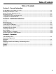
Table of Contents Table of Contents Section 1 - General Information Freight Damage and Claims Procedure......................................................................................................... 1-1 Model/Serial Number Location ...................................................................................................................... 1-1 Owner Warranty Registration Card..............................................................................................................
Table of Contents THIS PAGE INTENTIONALLY LEFT BLANK ii
Section 1 General Information Section 1 General Information Freight Damage and Claims Procedures 1. Shortages Check the number of cartons delivered against the quantity shown on your receipt. If the quantities do not match, have the driver note the shortage and file your claim with the freight company. 2. No-Fault Claim Procedure Manitowoc assumes responsibility for all freight damage claims involving participating carriers, with the following exceptions: • When the trucking company loses the equipment.
General Information Section 1 Owner Warranty Registration Card GENERAL The packet containing this manual also includes warranty information. Warranty coverage begins the day your new AuCS®A accessory is installed. Important Complete and mail the OWNER WARRANTY REGISTRATION CARD as soon as possible to validate the installation date.
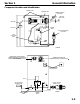
Section 1 General Information Component Location and Identification MOUNTING SLOTS DISPENSING PUMP COMMUNICATION WIRE (9 FEET LONG) VINYL TUBE (9 FEET LONG) VINYL TUBE CONTROL BOARD PLASTIC CAP ELECTRIC POWER CORD (8 FEET LONG) PUMP OSCILLATING DIODE SV1630G COMMUNICATION CONNECTION QDUAL COMMUNICATION WIRE IS SUPPLIED WITH ICE MACHINE AND IS LOCATED ON THE BACK OF THE CONTROL BOX COMMUNICATION CONNECTION COMMUNICATION WIRE IS SUPPLIED WITH AUCS® CLEANING FREQUENCY SELECTOR SWITCH RELAY ELECTRI
General Information Section 1 Compatible Ice Machine Models The AuCS®A accessory can be used on all Manitowoc ice machines capable of accepting the AuCS accessory. Q Model Undercounter (Q130, Q210, Q270) QM model (QM20, QM30, QM45) and Flake Ice Machines (QF800, QC700, QF400) are not AuCS compatible.
Section 2 Installation Instructions Section 2 Installation Instructions General Electrical Service These instructions are provided to assist the qualified installer. Check your local yellow pages for the name of the nearest Manitowoc Ice Machine Distributor or call Manitowoc Ice, Inc. for information regarding installation and start-up services. WARNING Improper installation will affect dispensing rate. Install only within the parameters outlined in this installation manual.
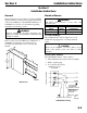
Installation Instructions Location/Mounting CAUTION Do not install in an area where the air temperature falls below 35°F or exceeds 110°F. The AuCS®A must be protected if it will be subjected to temperatures below freezing. Refer to “Removal From Service/Winterization.” HEIGHT REQUIREMENT (Refer to drawing on page 2-3.) Either the base or the top of the AuCS®A must be within 2” of the base of the ice machine. Do not mount the AuCS®A too high or too low. Section 2 3.
Section 2 Installation Instructions BASE OF ICE MACHINE NO! TOO HIGH 2” 5 CM 2” 5 CM BOX BASE OR BOX TOP MUST BE WITHIN 2” (5 CM) OF ICE MACHINE BASE NO! TOO LOW NOTE: BOX MUST ALSO MOUNT WITHIN REACH OF 9’ TUBING AND LOW VOLTAGE COMMUNICATION WIRE.
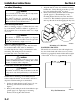
Installation Instructions Section 2 Connection to Ice Machine PVC CONDUIT FITTING (A) INSTALLATION GENERAL A ½” PVC CONDUIT FITTING B HOSE CLAMPS C LOCKNUT D BUMPER ½” LOCKNUT (C) ½” PVC CONDUIT FITTING (A) SV1636G PVC Conduit Fitting (A) Installation 1. Insert the PVC fitting (A) into the AuCS®A and tighten with the lock nut (C).
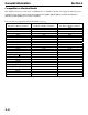
Section 2 Installation Instructions Connection to Ice Machine (cont.) Q200 Q280 Q450 Q600 Q800 Q1000 Q1300 Q1600 Q1800 Q320 Q370 Q420 Q600C Q800C Q1000C 1-1/8” DIAMETER ACCESS HOLE 1-1/8” DIAMETER ACCESS HOLE 5” 3” 1.5” 1.
Installation Instructions Section 2 IB600C IB800C IB1000C Q1400C 1-1/8" DIAMETER ACCESS HOLE 1-1/8" DIAMETER ACCESS HOLE 5.9" 7.5" 2" 3.0" QDUAL 1-1/8" DIAMETER ACCESS HOLE 7.
Section 2 Installation Instructions Connection to Ice Machine (cont.) PVC CONDUIT CONNECTION (NOT SUPPLIED) Connect the ½” PVC conduit from the AuCS®A to the ice machine. CAUTION Install 1/2” conduit to protect the tubing and modular wire from damage or access. NOTE: AuCS® SHOWN IS 115 VOLT WITH POWER CORD ATTACHED NOTE: A pulling elbow is recommended for easier routing of the vinyl tubing and modular wire.
Installation Instructions Section 2 Connection to Ice Machine (cont.
Section 2 Installation Instructions Q1400C ONLY A. 1/4" DIA x 4" LG VINYL TUBING B. 1/2" PVC CONDUIT FITTING (QTY 2) C. 90° THREADED ELBOW D. 1/4" FERRULE NUT E. 90° BARBED ELBOW F. 3/8" HOSE CLAMP (QTY 2) G. 1/2" LOCKNUT (QTY 2) A. Slide the 1/4" ferrule nut (part D) onto the 1/4" tubing (part A) B. Connect the 1/4" ferrule nut (with 1/4" tubing) to the 90° threaded elbow (part C) and hand tighten. C. Locate the 7/16" diameter hole in the bulkhead of the ice machine. (See illustration). D.
Installation Instructions Section 2 Connection to Ice Machine (cont.) Plug into the jacks on the ice machine control board and the AuCS®A control board. (Refer to drawing for routing communication wire in ice machine.) COMMUNICATION WIRE CONNECTION Insert the low voltage communication wire through the ½” conduit connecting the AuCS®A to the ice machine.
Section 2 Installation Instructions Connection to Ice Machine (cont.) VINYL TUBING CONNECTION 1. Insert the tubing into the ½” conduit from the AuCS® to the ice machine. 2. Slide the 3/8” hose clamp (B) onto the tubing and connect it to the barbed fitting on the AuCS® dispenser pump. AuCS® INLET WATER INLET 3/8” HOSE CLAMP (B) 8’ VINYL TUBING SV1644G MODULAR WIRE LEAD SV1643G Connecting Vinyl Tubing to Dispenser Pump Using 3/8” Hose Clamp (B) 3.
Installation Instructions Determine Type Of Solution Needed CAUTION Use only Manitowoc-approved Ice Machine Cleaner (part number 94-0546-3) or Sanitizer (part 94-0565-3) in the AuCS®A It is a violation of Federal law to use these solutions in a manner inconsistent with their labeling. Read and understand all labels on the bottles before use. The AuCS®A accessory will dispense Cleaner OR Sanitizer. It cannot dispense both at the same time. CAUTION Do not mix Cleaner and Sanitizer solutions together.
Section 2 Changing Solution Type CAUTION Do not mix Cleaner and Sanitizer solutions together. It is a violation of Federal law to use these products in a manner inconsistent with their labeling. Use the following procedure to flush the system prior to changing from Cleaner to Sanitizer or from Sanitizer to Cleaner. 1. Remove the bottle of Cleaner or Sanitizer from the AuCS®A. Insert a 16 oz. bottle of water. 2. Repeat the following until the water bottle is empty (approximately 8 times): A.
Installation Instructions Setting Frequency Of Cleanings The AuCS®A is factory-set to clean (or sanitize) the ice machine approximately once every two weeks. For less frequent cleaning, set the selector switch as indicated below. (Refer to “Component Location and Identification” for selector switch location.
Section 3 Ice Machine Operation Section 3 Ice Machine Operation Automatic Operation The following occurs when the toggle switch is in the ICE position: • • • The ice machine control board counts the number of ice harvest cycles.
Ice Machine Operation Section 3 Changing Switch Position During Automatic Operation Q MODELS/IB MODELS/SU1000C If the toggle switch is moved to OFF prior to the pump dispensing (less than 45 seconds into the cycle) then switched to: ICE CLEAN A normal ice-making mode begins. A manual clean cycle begins. Q1400C If the toggle switch is moved to OFF prior to the pump dispensing (less than 45 seconds into the cycle) then switched to: ICE CLEAN (See “Manual Start Operation,” page 3-1.
Section 3 QDUAL ONLY Manual Start Operation Step 1 Set the toggle switch to the OFF position after ice falls from the evaporator at the end of a Harvest cycle. Or, set the switch to the OFF position and allow the ice to melt off the evaporator CAUTION Never use anything to force ice from the evaporator. Damage may result. Step 2 To start the automatic cleaning system, move the toggle switch to the CLEAN position. The water will flow through the water dump valve and down the drain.
MANITOWOC ICE, INC. 2110 South 26th Street P.O. Box 1720 Manitowoc, WI 54221-1720 Phone: (920) 682-0161 Fax: (920) 683-7585 Web Site - www.manitowocice.com ©2002 Manitowoc Ice, Inc.