Reach-In Refrigerators and Freezers Installation, Use and Care Guide This manual contains important information regarding the installation and upkeep of your new Koolaire refrigerator or freezer. Please read the manual thoroughly prior to equipment handling, set-up, operation, and maintenance. Part No.
Safety Notices Procedural Notices As you work on a Manitowoc Koolaire reach-in, be sure to pay close attention to the safety notices in this manual. Disregarding the notices may lead to serious injury and/or damage to the equipment. As you work on a Manitowoc Koolairereach-in, be sure to read the procedural notices in this manual. These notices supply helpful information which may assist you as you work.
Table of Contents Table of Contents Section 1 - Warranty Model/Serial Number Location ........................................................................................................................ 1-1 Warranty ............................................................................................................................................................ 1-1 Warranty Service ..................................................................................................................
Table of Contents Table of Contents (cont.) Section 4 - Cleaning Exterior ............................................................................................................................................................... 4-1 Interior ................................................................................................................................................................ 4-1 Cleaning the Condenser Coil ........................................................................
Section 1 Warranty Section 1 Warranty Model/Serial Number Location The Koolaire data plate, which includes the model number and serial number, as well as important electrical and technical information, is located on the left interior wall of the cabinet at approximately eye level.
Warranty Section 1 THIS PAGE INTENTIONALLY LEFT BLANK 1-2
Section 2 Installation Section 2 Installation General CAUTION These instructions are of the utmost importance in assuring that the Manitowoc Koolaire cabinet operates as designed, and must be followed closely. Positioning the Cabinet CAUTION When selecting a permanent location for the cabinet, observe the following guidelines. Failure to do so may cause reduced performance and efficiency, cause damage, and void your warranty.
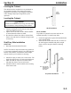
Installation Section 2 Uncrating WARNING Never attempt to tilt the cabinet alone. Always use two or more people when tilting the cabinet to remove the shipping skid or to move it through doorways. 1. Remove the bottom shipping skid using one of the methods below: • Lay the cabinet on its back, elevated and supported by wooden blocks. Remove the skid mounting bolts and separate the skid from the cabinet. • Tilt the cabinet from side to side and remove the mounting bolts.
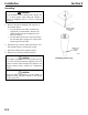
Section 2 Installation Leveling the Cabinet The cabinet must be leveled after it is positioned in its permanent location. This insures proper door alignment on all cabinets, and adequate condensate water drainage and proper refrigeration system operation. SHELF SUPPORT STANDARD SHELF CLIP Leveling the Cabinet CAUTION If casters are installed instead of legs, the floor must be leveled before final positioning of the cabinet. 1. Place a level on top of the cabinet. 2.
Installation Section 2 THIS PAGE INTENTIONALLY LEFT BLANK 2-4
Section 3 Start-Up Section 3 Start Up Electrical Requirements All cord-connected units should be plugged into a grounded and properly sized electrical outlet with appropriate overcurrent protection. Refer to the drawing below for electrical plug configurations. All permanently connected (hard-wired) units are fitted with a power junction box and 6” pigtail wires for power connection. Connect one end of the power line to the pigtail from the cabinet junction box.
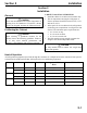
Start-Up Section 3 Electrical Specifications REACH-IN REFRIGERATORS Full Door Model Voltage/ Phase/Cycles Total Amps Maximum Fuse Size ANSI Electrical Plug Configuration KR-1 115/60/1 230/50/1 115/60/1 230/50/1 9.9 ** 10.4 ** Minimum circuit amps 15.1 ** 9.9 ** 10.4 ** Minimum circuit amps 15.1 ** 14.7 ** 16.0 ** Minimum circuit amps 15.
Section 3 Start-Up Condensate Water Removal (Refrigerators and Freezers) 24 HOUR DIAL Manitowoc cabinets are equipped with a condensate vaporizer system. This system uses energy-saving hot gas supplied by the refrigeration system lines. No drain connection is required. 2 HOUR DIAL Defrost Systems GENERAL Refrigerator coils operate at tmperatures below freezing (32°F). During compressor “off” time, the evaporator fan continues to circulate 38°F refrigerator compartment air through the evaporator coil.
Start-Up Section 3 Temperature Control REFRIGERATORS AND FREEZERS The temperature controls are factory-set to maintain an average temperature of 38°F (3°C) in refrigerators, and an average temperature of 0°F (18°C) in freezers. The temperature variance is 6-8 F (2°-4°C) degrees. A freezer should run between -2°F to +4°F (3°C to 15°C). A refrigerator should run between +35° to +42°F (1°C to 5°C).
Section 4 Cleaning Section 4 Cleaning Exterior Interior Clean cabinet exterior surfaces with a solution of mild soap and water. To minimize streaking, follow with a fresh water rinse. Clean cabinet interior surfaces with warm water and baking soda, applied with a cloth or sponge. If stainless steel becomes discolored, scrub only in the direction of the finished grain. For high shine, see your kitchen equipment dealer for a high-quality stainless steel polish.
Cleaning Section 4 Cleaning the Condenser Coil WARNING Disconnect electric power before cleaning. A dirty condenser restricts airflow, resulting in excessively high operating temperatures. This reduces efficiency and shortens component life. The washable aluminum filter is designed to catch dust, dirt, lint and grease. This helps keep the condenser clean. For efficient operation, it is very important to clean the condenser coil surface and keep it free of dust, dirt, and lint.
Section 5 Adjustments and Calibrations Section 5 Adjustments and Calibrations Adjustments Cabinet doors may require some adjustment after a period of usage, depending upon the frequency of door openings. This is normal. Follow the appropriate procedure below: SOLID DOOR ADJUSTMENT 1. Remove the metal hinge covers that conceal the three hinge mounting screws. Gently pry it off with a flat-bladed screwdriver. GLASS DOOR ADJUSTMENT To adjust the spring tension: 1.
Adjustments and Calibrations Thermometer Calibration Occasionally, the rigors of shipping and installation can shift the thermometer out of proper adjustment. If the accuracy of the thermometer is in question, place another thermometer inside the cabinet at approximately mid-height and compare the readings. If the thermometer requires adjustment, follow the procedure below. 1. Gently pry off the clear thermometer cover lens with a small flat-bladed screwdriver. 2.
Section 6 Before Requesting Service Troubleshooting Guide Section 6 Before Requesting Service Before requesting any service on your Manitowoc cabinet, please check the following points. This guide is not comprehensive; it is intended as a reference for solutions to common problems. Symptom Cabinet not running Condensing unit runs for long periods or continuously WARNING Disconnect electric power before performing any service. Possible Cause Fuse blown or circuit breaker tripped. Power cord unplugged.
Before Requesting Service THIS PAGE INTENTIONALLY LEFT BLANK 6-2 Section 6
MANITOWOCâ Koolaire. We reserve the right to make product improvements at any time. Specifications and design are subject to change without notice. 81 West Holly St. Parsons TN. 38363 Phone: (887) 582-5086 Service Fax: (901) 847-5552 Web Site - www.manitowocice.com ã2000 Manitowocâ Koolaire.