Soda Systems & SuperChil™ Refrigeration Units Technician’s Handbook This manual is updated as new information and models are released. Visit our website for the latest manual. www.manitowocfsg.
Safety Notices As you work on Manitowoc equipment, be sure to pay close attention to the safety notices in this handbook. Disregarding the notices may lead to serious injury and/or damage to the equipment. Throughout this handbook, you will see the following types of safety notices: ! Warning Text in a Warning box alerts you to a potential personal injury situation. Be sure to read the Warning statement before proceeding, and work carefully.
Read These Before Proceeding: ! Caution Proper installation, care and maintenance are essential for maximum performance and troublefree operation of your Manitowoc equipment. If you encounter problems not covered by this handbook, do not proceed, contact Manitowoc Foodservice Group. We will be happy to provide assistance. Important Routine adjustments and maintenance procedures outlined in this handbook are not covered by the warranty.
Table of Contents General Information Model Numbers . . . . . . . . . . . . . . . . . . . . . 9 How to Read a Model Number . . . . . . . . . 10 Accessories . . . . . . . . . . . . . . . . . . . . . . . 10 Special Applications . . . . . . . . . . . . . . . . 11 Model/Serial Number Location . . . . . . . . 11 Warranty Information . . . . . . . . . . . . . . . . 11 Installation Pre-installation Checklist . . . . . . . . . . . . . 13 Top Mounted Ice Maker Installations . . . 15 S250-M Dimensions . . . . . . . .
Start-up (Non-ERC) . . . . . . . . . . . . . . . . . Sequence of Operation (Non-ERC) . . . . Start-up (with ERC) . . . . . . . . . . . . . . . . . Sequence of Operation (with ERC) . . . . Equipment Setup Procedure (with ERC) Equipment Close Procedure — All Units 72 74 76 78 82 84 Troubleshooting Electronic Refrigeration Control (ERC) Model Error Codes . . . . . . . . . . . . . . . . . . . . . . . 87 Checklist . . . . . . . . . . . . . . . . . . . . . . . . . . 98 Problem Cross-reference Guide . . . . . .
ERC Component (Output) Connector Layout 154 ERC Sensor (Input) Connector Layout . 154 Component Specifications Refrigeration Unit Specifications . . . . . . 155 S-250M Specifications . . . . . . . . . . . . . . . 156 MII-302 Specifications . . . . . . . . . . . . . . . 156 Charts Refrigerant Charge . . . . . . . . . . . . . . . . . . 157 Operating Pressures . . . . . . . . . . . . . . . . 161 McDonald’s Models History . . . . . . . . . . . 163 Sustained Draw Curve Charts . . . . . . . . .
This Page Intentionally Left Blank 8 Part Number STH12 9/10
General Information Model Numbers This manual covers the following models: (A) Air Cooled (W) Water Cooled (R) Remote Cooled 2803A04 2803W04 2803R04 2803AX04 2803WX04 2803RX04 2803A04 2803W04 2803R04 11MA04 11MW04 11MR04 11MAX04 11MAW04 11MRX04 11MA04 11MW04 11MR04 42MA04 42MW04 42MR04 42MAX04T 42MWX04T 42MRX04T 44MA04 44MW04 44MR04 44MAX04T 44MWX04T 44MRX04T 44EAX04T 44EWX04T 44ERX04T 50MA04 50MW04 50MR04 50MAX04 50MWX04 50MRX04 50MA04Q/T 50MW04Q/T 50MR04Q/T SC1
How to Read a Model Number Condenser Type Model Base Model Prefix Model Suffix 11M A 04 x 2803 & SC180 - 1/3 hp 11M & SC340 - 1/2 hp 44M, 42M & SC1000 - 1 hp 44E - 1 hp, TUV Approved 50M & SC2000 - 2.
Special Applications ATTENTION: MARINE INSTALLATIONS ! Warning This unit is for use on vessels over 66 ft (20 m) in length. This unit must not be installed in the engine space of a gasoline-powered ship. NOTE: This unit must be secured to the vessel during installation. Models with part numbers beginning with the letters TS are NOT marine listed. OUTDOOR APPLICATIONS TS Multiplex Beverage Recirculating units are approved and listed by Underwriters Laboratories (UL).
Your warranty card must be returned to activate the warranty on this equipment. If a warranty card is not returned, the warranty period can begin when the equipment leaves the factory. No equipment may be returned without a written Return Materials Authorization (RMA). Equipment returned without an RMA will be refused at the dock and returned to the sender at the sender’s expense. Please contact your local distributor for return procedures.
Installation Pre-installation Checklist When installing any system, first make sure the major components are available.
Post Mix System: CO2 regulator set Beverage dispenser Beverage tubing CO2 tank Carbonator Stepless (Oetiker) clamps Chain for CO2 tank Double Check: Do you have enough space to install the dispenser or a dispenser and top mounted cuber? Does top mounted cuber (if utilized) have a minimum of 6 inches (15.
Also consider the location of the following items before installation: Water line Drain Power outlet Heating and air conditioning ducts Top Mounted Ice Maker Installations Location — Avoid placing the dispenser and/or ice machine near heat sources such as radiators, ovens, refrigeration equipment and direct sunlight. Clearances — Six inch (15.2 cm) clearance on all sides of the icemaker is needed.
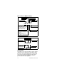
S250-M Dimensions A 39.81" (101.1 cm) B 30.00" (76.2 cm) C 9.94" (25.2 cm) D 4.44" (11.3 cm) E 22.63" (57.5 cm) F 28.00" (71.1 cm) G 31.13" (79.1 cm) H 20.00" (50.8 cm) I 27.44" (69.
S250-M FOOTPRINT A B D Maximum Area for Cutout C I E G Minimum Area for Cutout J H F A B C D E 30.00" (76.2 cm) 26.00" (66.0 cm) 8.00" (20.3 cm) 7.30" (18.5 cm) 11.00" (27.9 cm) F G H I J 15.00" (38.1 cm) 20.81" (52.8 cm) 3.00" (7.6 cm) 22.81" (57.9 cm) 31.13" (79.
MII-250 Dimensions Front View A B A 39.00" (99.1 cm) B 12.50" (31.8 cm) C 30.00" (76.2 cm) D 1.50" (3.8 cm) E 9.94" (25.2 cm) F 13.50" (34.3 cm) G 20.00" (50.8 cm) H 30.50" (77.5 cm) K 28.38" (72.1 cm) L 22.50" (57.2 cm) M 21.69" (55.1 cm) N 1.75" (4.4 cm) P 28.44" (72.
MII-250 FOOTPRINT A 3/8"-16 Thread Mounting Holes for Optional Legs Minimum area for Cutout: Install conduit to the back of opening to allow forward movement for service of flex manifold. B Maximum Area for Cutout C D I F H J E 3/4" NPT Fitting Drainpan G A B C D E 30.00" (76.2 cm) 26.00" (66.0 cm) 8.00" (20.3 cm) 8.00" (20.3 cm) 11.00" (27.9 cm) F G H I J 12.00" (30.5 cm) 13.50" (34.3) 22.00" (55.9cm) 24.00" (61.0 cm) 31.00" (78.
MII-302 Dimensions A B A 33.25" (84.5 cm) B 12.50" (31.8 cm) C 42.75" (108.6 cm) D 1.38" (3.5 cm) E 5.59" (14.2 cm) F 9.10" (23.1 cm) G 12.16" (30.9 cm) H 31.00" (78.7) J 15.78" (40.1 cm) K 28.78" (73.1 cm) L 22.50" (57.2 cm) M 0.82" (2.1 cm) N 26.97" (68.5 cm) O 30.47" (77.4 cm) P 33.75" (85.7 cm) Q 37.16" (94.
MII-302 FOOTPRINT A B Maximum Area for Cutout C Minimum area for Cutout: Install conduit to the back of opening to allow forward movement for service of flex manifold. E D J I F K 3/4" NPT Fitting Drainpan 0.50 (1.3) Cutouts for Extended Splash Panel Drain Tube H G A B C D 42.75" (108.6 cm) 38.75" (98.4 cm) 8.00" (20.3 cm) 8.00" (20.3 cm) E F G H 17.38" (44.1 cm) 12.00" (30.5 cm) 8.54" (21.7 cm) 12.63" (32.1 cm) I J K 20.50" (52.1 cm) 24.00" (61.0 cm) 31.00" (78.
MII-250 Installation Kit Syrup Tubes to Valves Carb Water to Left Manifold Plain Water to Left Manifold Carb Water to Right Manifold Plain Water to Right Manifold 1/2" ID Tubing from Conduit (5X) 3/8" ID Tubing from Conduit (7X) Use Only for One Conduit Plain Water Line Use Only for Two Conduit Carb Water Line Countertop To Conduit No. Part Number Description Qty.
MII-302 Installation Kit Carb Water to Left Manifold Plain Water to Left Manifold Syrup Tubes to Valves Carb Water to Right Manifold 1/2" ID Tubing from Conduit (9X) Plain Water to Right Manifold 3/8" ID Tubing from Conduit (7X) Use Only for One Conduit Plain Water Line Use Only for Two Conduit Carb Water Line Countertop To Conduit No. Part Number Description Qty.
down through the counter top, to connect to the conduit. It will also be necessary to fully insulate this new added section before passing through the counter top, or before hooking to main conduit. CARB WATER LINES • Unit has two carb water lines, one for each flex manifold. • Use 2 @ 1/2" x 1/2" elbow and 6-12" of 1/2" conduit tubing to make connection bend from unit down through hole in counter top, to mate with conduit. • Conduit with only two circulating carb water lines.
SYRUP LINES • Unit has eight syrup lines. • Use seven @ 1/4 x 3/8" and one @ 1/4 x 1/2" elbows and proper size conduit tubing to make connection bend from unit down through hole in counter top, to mate with conduit. • FULLY INSULATE (no air gaps) and finish with tape wrap, all these connections from unit, through 90° bend connection and down close to straight conduit connection. Locate unit properly on counter, and secure to counter.
REMOTE CONDENSER LINESET REQUIREMENTS Important If you have a MAC Multi-Pass condenser please add three (3) pounds additional charge. Important If you exceed the 100ft line set length add .72oz/ft of line set run (one way) for every foot over 100ft, to the UNIT charge 1. Both the discharge and liquid remote condensing lines must be kept to a minimum distance for maximum performance. All Multiplex systems are capacity rated to 100 ft (30.5 m) tubing distance between the compressor and condenser.
3. The easiest method to create a trap is to bend the tubing (smoothly, no kinks) into the trap form. Discharge Line Condenser Trap To the Condenser 3" (7.6 cm) x 6" (15.2 cm) Maximum Trap Area Discharge Line Trap Every 25 Vertical ft. (7.62 m) Compressor 3 ft (.9 m) (minimum) of Discharge Line Trap at the Compressor 4. The trap(s) must be of minimum height of 3" (7.6 cm) and a width of 6" (15.2 cm) to minimize oil accumulation. The traps can also be bent out of the refrigeration tubing.
Safe Installation Dos and Don’ts ! Warning Read the following warnings before beginning an installation. Failure to do so may result in possible death or serious injury. • Adhere to all National and Local Plumbing and Electrical Safety Codes. • Turn OFF incoming electrical service switches when servicing, installing, or repairing equipment. • DO NOT throw or drop a CO2 cylinder. Secure the cylinder(s) in an upright position with a chain. • DO NOT store CO2 cylinders in temperature above 125°F (51.
• DO check that all flare fittings are tight. This check must be performed with a wrench to ensure a quality seal. • DO inspect pressure on regulators before starting up equipment. • DO protect eyes when working around refrigerants. • DO use caution when handling metal surface edges of all equipment. • DO handle CO2 cylinders and gauges with care. Secure cylinders properly against abrasion. • DO store CO2 cylinder(s) in well ventilated areas.
Model 11M 100 ft / 30 m Maximum Conduit Length Model 44M 250 ft / 80 m Maximum Conduit Length Model 44M 250 ft / 80 m Maximum Conduit Length Model 50M 350 ft / 107 m Maximum Conduit Length Up to 12 gal / 45 L of syrup/day or 560 drinks/day (4,000 gal/year) Up to 21 gal / 79 L of syrup/day or 980 drinks/day (7,500 gal/yr) Up to 32 gal / 121 L of syrup/day or 1400 drinks/day (11,500 gal/yr) Up to 42 gal / 159 L of syrup/day or 2000 drinks/day (15,000 gal/yr) 2 Model 50M 350 ft / 107 m Maximum Conduit Le
Select a location for the refrigeration unit that meets the requirements of the building plans, local codes, and personnel. The unit must be positioned for free airflow as well as for future service. The following minimum requirements must be met: • 100 GPH (379 LTR/hr) potable water supply Models 2803/11/38; 200 GPH (757 LTR/hr) potable water supply Models 44/50 • Beverage quality CO2 gas (bulk or bottled supply) with a minimum 3/8" (.
3. Connect the water manifold supply line, located on the bulkhead panel in the motor compartment to the main water supply. The main water supply shut-off valve must remain in the OFF position. If a water filter is to be installed, connect the line to the outlet fitting of the filter. Plumb according to applicable plumbing codes. Bracket Bottom of Unit Screw Drain Hose Drain Hose Connection 4.
WATER SUPPLY 1. Use the built in fill valve that is already plumbed into the unit. 2. An appropriate floor drain is required within 6 ft (2 m) of the unit. 3. Potable water connections to the equipment must comply with the basic plumbing code of the Building Officials and Code Administrators International, Inc. (BOCA) and the Food Service Sanitation Manual of the Food and Drug Administration. Verify local plumbing code requirements.
Electrical GENERAL ! Warning All wiring must conform to local, state and national codes. MINIMUM CIRCUIT AMPACITY The minimum circuit ampacity is used to help select the wire size of the electrical supply. (Minimum circuit ampacity is not the unit’s running amp load.) The wire size (or gauge) is also dependent upon location, materials used, length of run, etc., so it must be determined by a qualified electrician.
Part Number STH12 9/10 120/60/1 230/50/1 120/60/1 230/50/1 208-230/60/1 230/50/1 120* /208-230/60/3 230/400/50/3 208-230/60/3 230/400/50/3 2803 & SC180 11M & SC340 44M, 42M & SC1000 50M SC2000 25.2 11.6 25.2 11.6 20.6 20.6 21.5 10.7 20.3 9.0 Minimum Circuit Amps 20A 15A 30A 20A 30A 25A 30A 16A 25A 16A Breaker 2.2 hp 2.0 kW 2.2 hp 2.0 kW 1 hp 1.9 kW 1/2 hp .97 kW 1/3 hp .46 kW Compressor * Only the model 50M with SS part numbers have 120V components, the TS does not.
GROUNDING INSTRUCTIONS ! Warning The unit must be grounded in accordance with national and local electrical codes. This appliance must be grounded. In the event of malfunction or breakdown, grounding provides a path of least resistance for electric current to reduce the risk of electric shock. NOTE: The refrigeration units are not equipped with a cord. ! Warning Improper connection of the equipment-grounding conductor can result in a risk of electric shock.
! Warning When using electric appliances, basic precautions must always be followed, including the following: a. Read all the instructions before using the appliance. b. To reduce the risk of injury, close supervision is necessary when an appliance is used near children. c. Do not contact moving parts. d. Only use attachments recommended or sold by the manufacturer. e. Do not use outdoors. f. For a cord-connected appliance, the following shall be included: • Do not unplug by pulling on cord.
Plumbing/Water Supply PLUMBING POTABLE WATER Model Required Water Pressure Drain Connections Water Supply 2803 & SC180 40 – 70 psig (2.8 – 4.9 bar) 3/4" ID within 6 ft (2 m) 3/8" ID EVA Line 11M & SC340 40 – 70 psig (2.8 – 4.9 bar) 3/4" ID within 6 ft (2 m) 3/8" ID EVA Line 44M, 42M & SC1000 40 – 70 psig (2.8 – 4.9 bar) 3/4" ID within 6 ft (2 m) 1/2" ID EVA Line 50M 40 – 70 psig (2.8 – 4.9 bar) 3/4" ID within 6 ft (2 m) 1/2" ID EVA Line SC2000 40 – 70 psig (2.8 – 4.
Preparing Ice Bank – Non-ERC BUILDING AN ICE BANK 1. At this time, fill the unit water bath tank to the top, or within 1/2" (1.3 cm) of the top minimum, of the overflow tube. Use a garden hose or another water supply to do this. NOTE: A manual fill valve is incorporated into the water circuit to the carbonator tank. This valve can be used to manually add water lost for any reason. Do not leave this valve ON constantly, only use it for filling and topping off.
5. Turn on the main water supply to the booster assembly. Verify the booster is plugged in and that the accumulator tank valve is open. (If the system has an optional “Out-of-Syrup” device, verify that it is unplugged.) 6. Verify the pump is running. Place the valve on the right side of the pump box in the purge position until all air bubbles have passed through the line. Turn the valve back to “dispense”. Plug the Out-of-Syrup device power cord into an appropriate wall outlet at this time (if supplied).
Preparing Ice Bank with ERC BUILDING AN ICE BANK 1. At this time, fill the unit water bath tank to the top, or within 1/2" (1.3 cm) of the top minimum, of the overflow tube. Use a garden hose or another water supply to do this. NOTE: A manual fill valve is incorporated into the water circuit to the carbonator tank. This valve can be used to manually add water lost for any reason. Do not leave this valve ON constantly, only use it for filling and topping off.
5. Turn on the main water supply to the booster assembly. Verify the booster is plugged in and that the accumulator tank valve is open. (If the system has an optional “Out-of-Syrup” device, verify that it is unplugged.) 6. Verify the pump is running. Place the valve on the right side of the pump box in the purge position until all air bubbles have passed through the line. Turn the valve back to “dispense”. Plug the Out-of-Syrup device power cord into an appropriate wall outlet at this time (if supplied).
Component Identification Typical System Conduit Conduit (In Wall) Air Compressor CO2 Panel Multiplex Refrigeration Unit Water Booster BIB Pumps CO2 Tank 6 Valve Soda Tower 8 Valve Soda Tower Part Number STH12 9/10 Water Filters BIB Rack Bag-In-Box (BIB) Syrup 43
Connections MODEL 2803 CONNECTIONS John Guest Fittings Right Hand Opening for Conduit Supply Lines 1/4" Plastic CO2 Line from Carbonator Control Switches Drain Hose 44 Part Number STH12 9/10
MODEL 11M CONNECTIONS Opening for Conduit Supply Lines Drain Hose Part Number STH12 9/10 John Guest Fittings Control Switches 45
MODEL 42, 44, & 50M CONNECTIONS John Guest Fittings Opening for Conduit Supply Lines Drain Hose ERC Controls 46 Control Switches (Non-ERC) Part Number STH12 9/10
ERC CONTROL BOARD OUTPUT CONNENCTIONS C R AGITATIOR CARB A CARB B CIRC A CIRC B L L/N EARTH PLUG THIS PIN Part Number STH12 9/10 47
HPCO SWITCH COM +5V DC OUTPUT HPCO 12 10 WATER TS 9 8 TD DISCHARGE TEMP WATER BATH TEMP COM +5V DC OUTPUT SUCTION TEMP CO2 11 TW 7 TB 6 TA 5 ICE 3 CA A 2 CA B 1 HIGH PROBE LOW PROBE GND HIGH PROBE LOW PROBE GND HIGH PROBE LOW PROBE GND LEVEL PROBE CIRC A TEMP CIRC B TEMP WL 4 ERC CONTROL BOARD INPUT CONNENCTIONS Part Number STH12 9/10
Maintenance Maintenance Schedule This section provides a list of periodic maintenance tasks and the scheduled frequency required to ensure the proper operation of your Multiplex dispensing equipment. To ensure quality beverages, prevent downtime, and reduce costs, these tasks must be performed as indicated. PERIODIC MAINTENANCE FOR SOFT DRINK EQUIPMENT (LISTED BY MAJOR COMPONENTS) Dispensing stations Daily (365 times per year) • Take temperature of finished drinks.
• • Inspect air compressor to verify cut-in at 70 psi (4.8 bar) and cut-out at 90 psi (6.3 bar). Adjust pressure switch if necessary. Inspect system for air leaks and repair as required. Refrigeration unit Every 4 months (3 times per year) • Clean the refrigeration unit air-cooled condenser using a vacuum cleaner. If equipped with watercooled condenser, verify the water discharge temperature is at 105°F (41°C). Adjust water modulating valve if necessary.
Syrup supply Daily (365 times per year) • Clean general area of syrup hookup with soap and warm water. Rinse off all soap. Every 4 months (3 times per year) • Inspect syrup lines for proper flavor identification labels. Replace labels if necessary. • Disconnect syrup containers. Clean connector with soap and warm water. Rinse with plain water and reconnect to syrup containers. CO2 gas supply Every 4 months (3 times per year) • Inspect pressure setting at CO2 high pressure regulator. Verify proper 90 psi (6.
• • • • • • • • • • • • • • 52 and syrup to water ratios at each dispensing station. Adjust as required. Inspect beverage conduits for damage. Reinsulate and seal any uninsulated areas. Inspect floor chases and seal any open chase ends. Inspect air compressor filter and replace if clogged. Air filter must be replaced every 6 months. Inspect air compressor to verify cut-in at 70 psi (4.8 bar) and cut-out at 90 psi (6.3 bar). Adjust pressure switch if necessary.
• • • • • • If pressure is low, inspect water filter cartridges to ensure they are able to supply adequate water pressure under normal system flow. Replace if unable to provide minimum 40 psi (1.4 bar) under load. Inspect syrup lines for proper flavor identification labels. Replace labels if necessary. Disconnect syrup containers. Clean connector with soap and warm water. Rinse with plain water and reconnect to syrup containers. Inspect pressure setting at CO2 high pressure regulator.
Cleaning and Sanitizing the Dispensing Valves and Product Lines MAINTENANCE SCHEDULE Every day Dispensing valves Remove nozzles and diffusers and soak in mild detergent cleaning solution. Scrub parts with small bristle brush taking care to clean small crevices and O-ring grooves. Turn OFF power to dispensing valves. Scrub exterior surfaces, including bottom splash area and actuator lever, with cleaning solution. Reassemble diffusers and nozzles. Wipe dry exterior surfaces before turning ON power.
CLEANING EQUIPMENT AND SUPPLIES • Recommended cleaner: Any caustic-base (low sudsing, non-perfumed, easily rinsed) detergent solution which provides a minimum 2% sodium hydroxide. The solution must be prepared in accordance with the manufacturer’s instructions. Solution temperature must be between 90°F (32°C) and 110°F (43°C). Temperatures in excess of this can cause internal damage to the dispensing valve components.
CLEANING AND SANITIZING PROCEDURE NOTE: Cleaning and sanitizing is not required for potable water circuits. Potable water lines must remain connected and operational during the cleaning and sanitizing procedures for syrup circuits. ! Caution It is required that the Carbonated Water Lines remain connected and operational during cleaning and sanitizing of the syrup circuits. Sanitizing of the valve without the Carbonated Water side operation may leave bacteria in the nozzle, diffuser, and syrup tube.
! Caution Do not allow cleaning and sanitizing solutions to remain in syrup systems longer than recommended contact time. Exceeding contact time will result in damage to valve components. 2. Flush the cleaning solution from the lines with clean water after a minimum of 3 minutes, by pulsing the valves as described above. 3. Remove the nozzles and the diffuser assemblies from the valves. Clean with cleaning solution. Agitate the assemblies to ensure assemblies are clean.
Sanitizing BEVERAGE SYSTEM CLEANING ! Warning Flush sanitizing solution from syrup system. Residual sanitizing solution left in system could create a health hazard. ! Warning When using cleaning fluids or chemicals, rubber gloves and eye protection must be worn. Sanitize the beverage system at initial start-up as well as regularly scheduled cleaning. The drain pan must be in place under soda valves, to carry away detergent and sanitizing agents that will be flushed through valves.
• Bucket 3 — mix a solution of unscented bleach (5% Na CL O) or commercial sanitizer and warm to hot water. Mixture should supply 100 PPM available chlorine (1/4 oz. bleach to 1 gallon water). 2. Disconnect the “syrup-line side” of the BIB connector. Bag side connector 3. Rinse connector with warm tap water.
4. Connect syrup connector to BIB connector and immerse both into Bucket 1. A “bag-side” connector can be created by cutting the connector from an empty disposable syrup bag. 5. Draw rinse water through system until clean water is dispensed. Most beverage valves allow the syrup side to be manually activated by depressing the syrup pallet. 6. Connect Bucket 2 to system. 7. Draw detergent solution through system until solution is dispensed. 8.
FIGAL BEVERAGE SYSTEM 1. Prepare the following in three clean Figal tanks: • Rinse tank - fill with room temperature tap water. • Detergent tank - mix approved beverage system cleaner with warm water as directed. • Sanitizing tank - mix a solution of unscented bleach (5% Na CL O) or commercial sanitizer and warm to hot water. Mixture should supply 100 PPM available chlorine (1/4 oz. bleach to 1 gallon water). 2. Disconnect all product and water lines from product tanks and remove carbonator. 3.
11. Reconnect syrup and carbonated water lines. 12. Draw syrup through the lines to rinse the system. Discard drinks until at least two cups of satisfactory tasting beverage are dispensed through the valve. Shipping, Storage and Relocation ! Caution Before shipping, storing, or relocating this unit, syrup systems must be sanitized. After sanitizing, all liquids (sanitizing solution and water) must be purged from the unit.
Operation How the Multiplex Works Model 2803 — a 1/3 HP refrigeration unit that will provide pre-mix carbonated beverages and chilled carbonated water for up to 6 gal (3 L) of syrup/day or 280 drinks/day (2,000 gal/yr) with a 40 ft (12 m) maximum conduit length. This is a remote refrigeration unit that derives its peak draw capacity from the reserve ice bank produced from a capillary tube refrigeration system. This system is controlled to cycle ON and OFF by the operation of the ice bank control.
Model 50M — a 2.2 HP Pre-mix refrigeration unit that will provide pre-mix carbonated beverages and chilled carbonated water for up to 42 gal (159 L) of syrup/day or 2,000 drinks/day (15,000 gal/yr) with a 350 ft (107 m) maximum conduit length. This refrigeration unit is a remote refrigeration unit that derives its peak capacity from the reserve ice bank produced by the operation of the compressor. This system is controlled to cycle ON and OFF by the operation of the ice bank control.
• The TS compressor is mounted with bolts instead of studs. • TS remote and water-cooled back panel connections are offset to protect fittings.
• TS air-cooled condenser comes standard with a filter. WATER MANIFOLD TS Two Stainless Steel log style manifolds • One regulated supply for carbonator pumps. • One unregulated supply for non-carb drinks and water bath fill. Other Connections • Connections are made in the water bath compartment. • Separate plain water manifold eliminates need to plug off during installation.
ELECTRICAL TS • Electrical compartment has been moved up on the unit to eliminate water intrusion potential from the pump compartment. • All components are now 208/230V. This eliminates the need for a neutral wire. • New unit has service connections in the electrical compartment. Allows more room to work and more reliable connection. • Pump protection switch has been moved to the pump compartment to eliminate potential leak point in electrical compartment.
WATER BATH ACCESS SS • Has a round hole in the front and back panels with no edge trim to protect lines. • End panel has two ovals in the rear of the panel with edge trim to help protect conduit lines. WATER BATH ACCESS TS • All panels have large oval access holes with interchangeable covers. • Front panel has 3 hole cover for water and CO2 line routing. • Back panel has solid cover. • End panel has one open cover and one solid cover. • Open cover provides wide ledge for conduit line protection.
SERVICE ACCESS SS • Front panel was solid and did not allow easy access for service. • Switch panel was mounted flush to end panel. SERVICE ACCESS TS • Front panel is split to allow front access to the compressor compartment. • Switches are recessed and the edge has trim panel to protect fingers from sheet metal edges.
SERVICE ACCESS TS WITH ERC LED Display PGM SER CIRC B COMP/ AGIT Service Switch CARB A CARB B CIRC A CIRC B Program Switch • Service Switch — (SER) switch, press to send ID on power line network. • Wink Function — LED flashes “Ion” to indicate wink function. Press program switch (PGM) to disable wink function.
Equipment Setup Procedure (Non-ERC) 1. Ensure that all valve nozzles are attached to the valves. 2. Observe pressure of CO2 high pressure tank of 500 psi (34 bar) or more, or bulk CO2 tank of 150 psi or more. Primary regulator set at 90 psi (6 bar) and the secondary regulator set at 35 psi (2.4 bar). 3. Observe the control panel to verify that all pressure gauges are set at correct operating pressures. 4.
Start-up (Non-ERC) 1. Fill the refrigeration unit water bath tank with water to within 1/2" (1.27 cm) of the top of the overflow tube. 2. Open the manual water shut-off valve to the water cooled condenser (if applicable). 3. Turn ON the rocker switch labeled “Refrigeration” to begin building an ice bank. 4. Turn ON the rocker switch labeled “Agitator”. NOTE: On TS units 3 & 4 are combined into 1 switch. 5. Ice will begin to form on the evaporator coils in approximately 2 hours. 6.
PLACING THE CARBONATION SYSTEM IN OPERATION 1. Open the CO2 gas supply valve at CO2 tanks or bulk tank. Adjust the CO2 pressure to 90 psi (6.2 bar). 2. Open relief valve on top of the carbonator tank for 4 seconds to bleed off air in tank. 3. Turn ON the water supply to unit. 4. Turn ON the switch labeled “Carbonator Pump”. Allow carbonator to run and cycle OFF. 5. Activate all valves until a smooth, continuous flow of carbonated water and non-carbonated water appear at the valves. 6.
Sequence of Operation (Non-ERC) PRE-MIX REFRIGERATION UNIT Ice Bank Is Required 1. Check water bath for full ice bank. 2. The stabilized water bath operating temperature must be maintained at 33°F (0.6°C) to 35°F (1.7°C). The following is a sequence of operations for the Multiplex Pre-mix Beverage equipment. 1. Once a drink is dispensed, the following will occur: A. For a Syrup Tank System, the Pre-mix syrup is manually mixed at the store.
Conduit Conduit (In Wall) Air Compressor CO2 Panel Multiplex Refrigeration Unit Water Booster BIB Pumps CO2 Tank 6 Valve Soda Tower 8 Valve Soda Tower Water Filters BIB Rack Bag-In-Box (BIB) Syrup Multiplex Pre-mix Beverage System Operation and Layout Part Number STH12 9/10 75
Start-up (with ERC) PLACING EQUIPMENT IN OPERATION Before placing equipment in operation, verify that all requirements for roof mounted Remote Condenser Units (if applicable) have been satisfied. Refer to the instructions on installing the Remote Condenser. Verify proper supply power to unit. 1. Fill the refrigeration unit water bath tank with water to within 1/2" (1.27 cm) of the top of the overflow tube. 2. Open the manual water shut-off valve to the water cooled condenser (if applicable).
PLACING THE SYRUP SYSTEM IN OPERATION 1. Open the CO2 gas supply valve at CO2 tanks or bulk tank. Adjust the CO2 pressure to 90 psi (6.2 bar). 2. Open relief valve on top of the carbonator tank for 4 seconds to bleed off air in tank. 3. Verify the water supply to unit is on. 4. Press the switch labeled “Carb A” (and B if applicable). Allow carbonator to run and cycle OFF. 5. Press the switch labeled “CIRC A” (and “CIRC B” if applicable). 6.
Sequence of Operation (with ERC) ELECTRONIC CONTROL Prerequisites • Potable water must be connected to the carbonator pump circuit. • The ice bank water bath water must cover the evaporator. The compressor will not start unless the ice bank control probes are immersed in water. • CO2 must be supplied. Initial Power-up The control has a 30-second delay when power is connected, or disconnected and reconnected. The display will show Pd30 - power delay and 30 seconds left in the countdown cycle.
Power Interruption During a power interruption the control will resume from the point of interruption when power is reapplied and the time delay expires. Any switches/components that were energized when power was interrupted will be energized when power is reapplied.
PGM Switch • Used to enter and exit programming modes.
• • Press and hold Carb B switch — Display will indicate one of the following: • Cb00 — Low and High Probes are open (carbonator motor is energized) • Cb11 — Low and High Probes are closed (carbonator motor is de-energized) • Cb01 — Low Probe closed (Motor will still be on) Press and hold COMP/AGIT switch — Display will indicate one of the following: • CL 0 — Water level low • CL 1 — Water level OK Program Mode 2 Add circulation pumps C & D. • Press PGM button for 3 seconds — Display shows 0001.
Program Mode 4 Temporarily cancel display of error codes. Cancelling the error codes allows circulating glycol temperatures to be displayed until the error can be corrected. • Press PGM button for 3 seconds — Display shows 0001. • Press PGM button three times — Display shows 0004 program mode 4. • Wait 3 seconds — Display shows -004 = All error codes will be displayed during run mode. • Press COMP/AGIT button once — Display shows ---4 = error codes will not be displayed during run mode.
Part Number STH12 9/10 COMPRESSOR DELAY SHOWS “Cd99” AND COUNTS DOWN TO “Cd00” POWER UP DELAY SHOWS “Pd30” AND COUNTS DOWN TO “Pd00” COMPRESSOR COMES ON AFTER DELAY, IF CONTROL CIRCUIT REQUIRES YES COMP/AGIT SWITCH ON NORMAL RUN MODE DISPLAY SHOWS CIRC WATER TEMP(S) OR WATER BATH TEMP IN BEER E1 = LOW WATER PRESS E2 = LOW CO2 PRESS E3 = LOW WATER BATH LEVEL E4 = HIGH WATER BATH TEMP E5 = HIGH WATER PRESS E6 = HIGH REFRIGERATION TEMP E7 = LARGE ICE BANK E8 = LONG CARB A RUN TIME E9 = LONG CARB B RUN TI
Equipment Close Procedure — All Units 1. Clean the underside of the dispensing tower around the nozzle area with a clean damp towel. 2. Pour at least 60 oz (1.8 liters) of warm water down the drain openings.
Part Number STH12 9/10 COMPRESSOR DELAY SHOWS “Cd99” AND COUNTS DOWN TO “Cd00” COMPRESSOR COMES ON AFTER DELAY, IF CONTROL CIRCUIT REQUIRES YES NO YES NO EXIT PROGRAM MODE ENTER PROGRAM MODE E1 = Low Water Suply Pressure E2 = Low Co2 Pressure E3 = Low Water Level - Water Bath E4 = High Water Bath Temperature E5 = High Water Supply Pressure E6 = High Refrigeration Temperature E7 = High Ice Bank Size (Probe Sensor 2) E8 = Long Carb A Run Time E9 = Long Carb B Run Time Shorted Transducer = "----" Open T
Part Number STH12 9/10 PRESS PGM SWITCH ONCE (1) PRES CIRC A SWITCH TO SHOW WATER LEVEL PROBE “CL_1” = WATER “CL_0” = LOW WATER (E3) PRESS CARB A SWITCH TO SHOW LLC PROBE “CA00” = NO WATER CARB A MOTOR ON “CA01”= LOW SENSOR IN WATER, MOTOR ON “CA11” = LOW & HIGH SENSOR IN WATER, MOTOR OFF REPEAT ABOVE FOR CARB B SWITCH “CbXX” PRESS COMP/AGIT SWITCH TO SHOW ICE BANK PROBE “CC11” = NO ICE COMPRESSOR ON “CC10”= ICE ON LOW SENSOR COMPRESSOR OFF “CC00” = ICE BANK TOO LARGE (E7) “C000”(CONDUCTIVITY) PRES
Troubleshooting Electronic Refrigeration Control (ERC) Model Error Codes • • • • Error codes will interrupt the temperature display and stay active until the error is corrected. If multiple errors are present, the errors will rotate and display every 5 seconds. Resetting errors — After correcting the problem, the respective switch for the error must be cycled OFF and then ON to reset. Disconnecting and reconnecting power will erase all errors.
YES DISPLAY PRESSURE >15 PSI PRESS CARB A BUTTON TO VERIFY WATER PRESSURE“PXXX” GO INTO PROGRAM MODE 1 PRESSURE READOUT “P000” NORMALLY CAUSED BY WATER PRESSURE <5 PSI FOR 5 SECONDS MUST STAY ABOVE 10 PSI TO CORRECT EI NO E3 NOTE: THAT ALL CARB MOTORS AND ALL CIRC MOTORS WILL GO OFF, WITH THIS ERRORCOMPR ESSOR AND AGITATOR STAY ON E2 E5 YES DISPLAY PRESSURE >20PSI PRESS CARB B BUTTON TO VERIFY CO2 PRESSURE “PXXX” PSI GO INTO PROGRAM MODE 1 PRESSURE READOUT “P000” NORMALLY CAUSED BY CO2 PRE
Part Number STH12 9/10 89 REPLACE WATER PRESS TRANSDUCER 020001992 YES REPLACE CO2 PRESS TRANSDUCER 020001992 YES NO SUPPLY PRESSURE >20PSI SUPPLY PRESSURE >15PSI NO VERIFY CO2 SUPPLY PRESSURE TO UNIT, >20PSI OR NOT, WITH ANOTHER GAUGE IN THE SUPPLY SYSTEM TROUBLESHOOT WATER SUPPLY SYSTEM, TO FIX LOW WATER PRESSURE CONDITION YES REPLACE ERC CIRCUIT BOARD 020001985 E VERIFY INCOMING WATER SUPPLY PRESSURE TO UNIT >15 PSI OR NOT WITH ANOTHER GAUGE IN THE SUPPLY SYSTEM REPLACE ERC CIRCUIT BOARD 020
E2 YES VERIFY TEMP WITH SECOND THERMOMETERIF STILL <45°FREPLACE ERC BOARD 020001985 NO WATER BATH TEMP DISLAY >45 °F GO INTO PROGRAMMING MODE 1, “F000”PRESS CARB A BUTTON TO SHOW WATER BATH TEMP“FXXX” °F NORMALLY CAUSED BY WATER BATH TEMPERATURE > 45°F EI E3 E5 E6 NO NO VERIFY PRESSURE WITH SECOND PRESS GAUGE YES WATER PRESS >75 PSI GO INTO PROGRAMMING MODE 1, “P000”PRESS CARB A BUTTON TO SHOW INCOMING WATER PRESSURE “PXXX” PSI NORMALLY CAUSED BY WATER PRESSURE >75 PSI, E4 E7 E9 YES
Part Number STH12 9/10 91 NO REPLACE WATER BATH THERMISTOR 020002142 GO TO COMPRESSOR TROUBLESHOOTING TO FIX REFRIGERATION SYSTEM YES TEMPERATURE VERIFIED VERIFY TEMPERATURE WITH SECOND THERMOMETER NO VERIFY PRESS WITH SECOND GAUGE, IF CORRECTREPLACE ERC BOARD 020001985 REPLACE WATER PRESSURE TRANSDUCER 020001992 TROUBLE SHOOT WATER SUPPLY SYSTEM TO FIX.
E2 YES UN-PLUG CARB B CONNECTOR FROM ERC (#1) TO VERIFY CONDUCTIVITY OK VERIFY ICE BANK PROBE INSTALLED CORRECTLYPLASTIC STEP ON PROBE AWAY FROM EVAP NO PIN #2 COVERED IN ICE VERIFY VISUALLY THAT ICE IS OVER ICE BANK PROBE PIN #2 (MIDDLE PIN) NORMALLY CAUSED BY ICE ON ICE BANK PROBE PIN #2 (MIDDLE PIN) EI E3 E5 E6 NO THEN CHECK FOR PUMP OUTPUT(32 OZ IN LESS THAN 20 SEC) FIX LEAK YES LEAK IN SYSTEM FIRST CHECK FOR LEAK IN CARB SYSTEM NORMALLY CAUSED BY CARB MOTOR A RUNNING > 7 MINUTES CO
Part Number STH12 9/10 93 YES REPLACE ICE BANK PROBE 020002091 YES “E7” ERROR GOES AWAY NO UN-PLUG ICE BANK PROBE CONNECTOR (#3) FROM ERC BOARD NO “E7” ERROR GOES AWAY REPLACE ERC CONTROL BOARD IF PROBLEM CONTINUES 020001985 COMPRESSOR ON TOO LONGGOTO COMPRESSOR / REFRIGERATION TROUBLESHOOTING YES PUMP GOOD IF “E8” AND/OR “E9” CONTINUE TO OCCUR REPLACE ERC CONTROL BOARD 020001985 RESET ERROR (PUSH CARB A AND/OR B BUTTON OFF, THEN ON TO RESET NO REPLACE PUMP
COMPRESSOR WILL NOT COME ON VERIFY ICE BANK PROBE TIP #1 IN ICE COMPRESSOR WILL STILL NOT GO OFF PULL CARB A CONN TO RESET CONDUCTIVE PROBES NO COMPRESSOR WILL STILL NOT COME ON VERIFY KEYPAD/DISPLAY GOOD, SEE KEYPAD / DISPLAY TROUBLE SHOOTING PAGE 7 COMPRESSOR WILL NOT GO OFF COMPRESSOR CHECK (LIQUID LINE TEMP) AND EVAP OUT TEMP IF COMPRESSOR COMES ON AND STILL NO COOLING, USE REFRIGERATION TROUBLESHOOTING CHECK CONNECTORS AND WIRING TO FAN / REMOTE CONDENSERCHECK MOTORS OUTPUT TERMINALS ARE
Part Number STH12 9/10 95 REPLACE ERC CONTROL BD 020001985 ELSE REPLACE ICE BANK PROBE 020002091 PULL ICE BANK CONN ON ERC, COMPRESSOR SHOULD GO OFF NO YES VERIFY PROPER VOLTAGE AT COMPRESSOR NO NO VERIFY VOLTAGE AT CONTACTOR COIL VERIFY VOLTAGE AT COMP OUTPUT TERMINALS ON ERC VERIFY HPCO SWITCH CLOSEDSHORT CONN 12 SHORT ICE BANK YES CONNECTOR #3ALL PINS PROBES NO REPLACE COMPRESSOR CHECK CONNECTO RS AND WIRING TO CONTACTOR COIL REPLACE ERC CONTROL BD 020001985 REPLACE HPCO SWITCH REPLAC
Part Number STH12 9/10 CARB MOTOR DOES NOT TURNOFF “CX00” CARB MOTOR SHOULD BE ON YES / END YES / END VERIFY VOLTAGE AT CIRC OUTPUT TERMINALS ON ERC VERIFY KEYPAD / DISPLAY WORKS, CIRC LED GOES ON AND OFF VERIFY NO “E1” ERROR CIRC MOTOR DOES NOT TURNON CIRCULATING SYSTEM A OR B CIRC MOTOR DOES NOT TURNON FIRSTVERIF Y PRG MODE 2 IS SET TO “002”FOR BOTH CARB PUMPS “CX11” CARB MOTOR SHOULD BE OFF PRESS CARB A AND/OR CARB B BUTTON, VERIFY CARB A AND/OR B CONDUCTIVITY PROBES “CX__” X= A OR B VER
Part Number STH12 9/10 97 REPLACE ERC CONTROL BOARD 020001985 CHECK ALL WIRES AND CONNECTORS FOR OPEN ON CARB TANK WIRING HARNESSCHECK CARB MOTOR YES VOLTAGE AT ERC AGIT OUTPUT TERMINALS NO NO REPLACE ERC CONTROL BOARD 020001985 YES VOLTAGE AT ERC AGIT OUTPUT TERMINALS NO NO/ END REPLACE KEYPAD / DISPLAY IF BAD 020001986 ORIF WIRES/MOTOR OK, REPLACE ERC BOARD 020001985 CHECK ALL WIRES AND CONNECTORS TO CIRC MOTOR, CHECK CIRC MOTOR NO GENERAL NOTE: FOR DISPLAY PROBLEMS, IF COUNTDOWN OCCURS ON
Checklist If a problem arises during operation of your post mix soda refrigeration unit, follow the checklist below. Routine adjustments and maintenance procedures are not covered by the warranty. ! Warning Only trained and certified electrical and plumbing technicians must service this unit. All wiring and plumbing must conform to national and local codes. Problem Possible Cause To Correct Water only dispensing: No pressure Regulator(s) out of adjustment Check/adjust regulator(s).
Problem Possible Cause To Correct Beverage dispensed is too sweet: Is the ratio (brix) of the drink correct? Flow control out of adjustment Adjust the flow control. Insufficient soda flow due to low carbonator pressure Adjust CO2 pressure or change the tank. Low CO2 pressure due to leaks Repair CO2 leaks. Obstruction in the water or soda line Clean out the lines. Flow control out of adjustment Adjust the flow control. Soda flow too high Reset CO2 pressure or replace regulator if necessary.
No carbonated water X X Carbon particles in drink X X X R Flat drinks X X R X X X X X R R X Peculiar taste carbonated water X Peculiar taste non-carbonated water R X R X Peculiar taste syrup X Carb and booster pump noisy X R X X R R X Too much syrup X R Too much carbonated water X Too much non-carbonated water X Foaming X R R Booster pump/motor won’t cycle OFF X Booster pump/motor won’t cycle ON X X X Low pressure CO2 alarm won’t cycle OFF X Water found in prima
CO2 Gas System On units not equipped with Air Pump, check all Probable Causes listed below. Qualifier Probable Cause If leak occurs while Change-over valve is positioned on Air, follow the “Probable Causes” (for units equipped with Air Pump). CO2 Tank leaking. Use a soap solution around CO2 Tank valve Stem to locate leaks. If leaks are present, bubbles will appear. If valve Stem leaks at Tank, replace CO2 Tank. CO2 Washer damaged or missing.
Qualifier Probable Cause Corrective Action Flat drinks (lack of carbonation in carbonated water) Primary Regulator (less than 500 psi [34.5 bar]). CO2 Supply exhausted (CO2 Tank is functionally empty if pressure reads less than 500 psi [34.5 bar]). Verify CO2 Tank pressure is a minimum of 500 psi (34.5 bar) on the Primary Pressure Regulator Gauge marked 0-2000 psi. Replace tank if necessary. Primary Regulator out of adjustment or inoperative. Verify CO2 Primary Regulators are set at 90 psi (6.
Qualifier Probable Cause Corrective Action Flat drinks (lack of carbonation in carbonated water) (continued) Low Pressure CO2 Warning light or buzzer does not go OFF. Water found in CO2 Regulator and lines. Leaks on system. If leaks exist on CO2 System, not enough pressure is maintained to allow Pressure Switch to cut OFF CO2 Warning light or buzzer. Use a soap solution to located possible leaks. Tighten connections carefully. Primary Regulator out of adjustment. Check CO2 supply.
Carbonated Water System Qualifier Probable Cause Corrective Action Flat drinks Malfunctioning of Refrigeration System. Beverages at dispensing tower are above 40°F (5°C). Malfunctioning of Circulating System. Beverages at dispensing tower are below 40°F (5°C). Refer to Troubleshooting “Refrigeration System” under Warm drinks. Refer to Troubleshooting “Circulating System” under Warm drinks. CO2 supply exhausted.
Qualifier Probable Cause Corrective Action Beverages at Dispensing Tower are below 40°F (5°C). (continued) Back Flow Preventer. Remove top cover from Remote Refrigeration Unit. Use a soap solution around Back Flow Preventer. If bubbles appear at Vent Hole or underside of Back Flow Preventer, clean or replace Back Flow Preventer and corresponding Water Check valve carbonator Tank. Double Check valve (water) stuck open.
Qualifier Probable Cause Corrective Action No carbonated water at any of the dispensing valves No CO2 gas or water present at dispensing valves. CO2 gas is present at dispensing valves but no water. 106 Malfunction of Refrigeration System. Refer to Troubleshooting “Refrigeration System” under No carbonated water at any of the dispensing valves (freeze up). Malfunction of Circulating System. Refer to Troubleshooting “Circulating System” under No carbonated water at any of the dispensing valves.
Qualifier Probable Cause Corrective Action No carbonated water at any of the dispensing valves (continued) CO2 gas is present at Dispensing Valves but no water. (continued) Carbonator Pump worn (Brass pump). Dispense Carbonated Water while listening for carbonator pump and motor to cycle ON at Refrigeration Unit. Pumps should operate between 6 to 12 seconds before cycling OFF. If operating time exceeds 30 seconds, carbonator Pumps is worn, replace Pump. Motor defective.
Qualifier Probable Cause Corrective Action Carbonator pump and motor will not cycle OFF (possibly noisy pump) Little or no carbonated water at dispensing valve. 108 Primary CO2 Regulator adjusted at extremely high pressure. Verify CO2 Primary Regulators are set at 90 psi (6.3 kg/cm2). Adjust if necessary. If regulator will not star in adjustment, replace regulator. Water supply to Carbonator Pump shut-off or restricted. Verify water to unit by observing Filtered Water Pressure Gauge.
Qualifier Probable Cause Corrective Action Carbonator pump and motor will not cycle OFF (possibly noisy pump) (continued) Carbonated water at dispensing valve. Peculiar taste in carbonated water only. Liquid Level Control defective. Shut OFF main power supply to unit and push Toggle Switch for Carbonator and Circulator to the OFF position. Remove Electrical Access Panel from Refrigeration Unit and locate Liquid Level Control. Strip a 1-1/2" (3.
Qualifier Probable Cause Corrective Action Carbonator pump and motor will not cycle OFF (possibly noisy pump) (continued) Carbon particles in furnished drink. Carbonator Motor cycles ON and OFF in short cycles. 110 Malfunction of Water Filter. Refer to Troubleshooting “Water Filter System” under Carbon particles in finished drinks. Defective Carbonator Pump. Remove top cover from Refrigeration Unit. Loosen Coupling Clamp with a flat-blade screwdriver and disengage pump from motor.
Circulating System Qualifier Probable Cause Corrective Action Warm drinks Drinks warm throughout the day, warm all the time. Malfunction of Refrigeration System. Refer to Troubleshooting “Refrigeration System” under Warm drinks (carbonated water temperature over 40°F [5°C]). Drinks warm during periods of low demand, much colder during periods of high demand. No power to Circulating Motor. Verify Switch to Circulating Motor is in the ON position and Main Power Supply is ON.
Compressed Air System Until repairs can be made on Compressed Air System, place Air/CO2 Change-over Valve in the CO2 Operating position. Qualifier Probable Cause Corrective Action No syrup Air Compressor will not cycle ON and Air Pressure Gauge registers 0 psi. Air Compressor cycles ON and OFF and Air Pressure Gauge readings range between 70 psi (4.9 kg/cm2) to 90 psi (6.3 kg/cm2). 112 No power to Air Compressor.
Qualifier Probable Cause Air Compressor operates excessively. Leak at Shake Machine, Orange Juice Dispenser or other optional equipment. Turn air supply to Shake Machine to OFF position. If Air Compressor cuts out and maintains pressure, leak is at Shake Machine or Orange Juice Dispenser. Refer to manufacturer’s manual for Troubleshooting. Leak at Compressed Air System. Use a soap solution around all connections starting from the Air Motor/Pump assembly to the Low and Medium Pressure Syrup Regulators.
Dispensing Valve and Tower Qualifier Probable Cause Corrective Action All corresponding valves dispensing no syrup. Malfunction of syrup system. Refer to Troubleshooting “Syrup System” under No syrup or insufficient syrup in finished drink. No syrup at only one dispensing valve. Syrup Shut-off Valve closed or partially closed. Remove top cover from Dispensing valve or Tower. Locate Syrup Shut-off Valve on right hand side of Dispensing valve. Verify shut-off is turned fully open.
Qualifier Probable Cause Corrective Action No carbonated water or insufficient carbonated water in finished drink No Carbonated Water only at one dispensing valve. Carbonated water Shut-off Valve closed or partially closed. Remove top cover from Dispensing valve or Tower. Locate Carbonated Water Shut-off Valve on left hand side of Dispensing valve. Verify Shut-off Valve is turned fully open. Mounting Block restricted. Remove Dispensing valve from Mounting Block.
Qualifier Probable Cause Corrective Action No water or insufficient water in finished drinks All valves dispensing noncarbonated drinks no water. Water Shut-off Valve closed or partially closed. Problem occurs at only one dispensing valve. Refer to Troubleshooting “Water Booster System” under Low or No Water Pressure at Noncarbonated Beverages. Refer to this section on No carbonated water at only one dispensing valve in the dispensing valve.
Qualifier Probable Cause Corrective Action No water or insufficient water in finished drinks (continued) Problem occurs at all valves on one (1) dispensing tower. No power to transformer or transformer defective. Verify power with a voltmeter at wall outlet. Verify power across low voltage leads on transformer. If 24 volts are present ON and OFF Toggle Switch is defective. Replace. Problem occurs at only one (1) dispensing valve. Dispensing tower’s ON and OFF is Switch defective.
Qualifier Probable Cause Corrective Action No water or insufficient water in finished drinks (continued) Foaming of finished products. Unit totally inoperative; all electrical switches in the ON position. 118 Nozzles, Syrup Tube Diffusers dirty. Remove and clean Nozzle Assemblies and reassemble. Warm drinks. Refer to Troubleshooting “Refrigeration System” under Warm drinks. Incorrect pressure on syrup. Verify pressure supplied to sugar base products is at 60 psi (4.2 kg/cm2).
Electrical System Qualifier Probable Cause Corrective Action Fuse/Circuit Breaker is open. Short Circuit or overload within unit. Push Toggle Switches labeled carbonator and circulator to the OFF position. Push the Toggle Switches for Booster Pump, Air Compressor, Agitator and Refrigeration to the OFF position. Replace fuse(s) and reset circuit breaker. Push the Toggle Switches ON in the following sequence as labeled below, to locate short or overload within unit, waiting momentarily between steps.
Refrigeration System Until repairs can be made on unit with no Ice Bank, push Refrigeration and Agitator Switch to the OFF position and ice down Bath using ice from Ice Maker. Qualifier Probable Cause Corrective Action Warm drinks (carbonated water temperature over 40°F [5°C]) Compressor operates but no ice present at water bath. Compressor operates but no ice present at water bath. 120 Water Bath Feeder Valve inoperative (not enough water in bath). Remove tope cover from Remote Refrigeration Unit.
Qualifier Probable Cause Corrective Action Warm drinks (carbonated water temperature over 40°F [5°C]) (continued) Compressor operates with Ice present at water bath. Compressor won’t operate and no ice at water bath. Defective Agitator Motor Assembly. Remove top cover from Remote Refrigeration Unit. Examine the Agitator Motor Assembly, ensure propeller is secured to Agitator and that the Agitator Switch is in the ON position, allowing the water in Bath to be agitated across the cooling coils.
Qualifier Probable Cause Corrective Action No carbonated water at any of the dispensing valves CO2 gas is present at dispensing valves but no Carbonated Water. Malfunctioning of Carbonating System. No CO2 Gas or water present at dispensing valve. On units equipped with the “Red” Refrigeration Warning Light. Refrigeration Warning Light cycles ON and OFF with Compressor. 122 If CO2 gas is present at the Dispensing Valves and there is no water, the problem is in the Carbonated Water System.
Syrup System Qualifier Probable Cause Corrective Action No syrup or insufficient syrup in finished drink. Syrup Tank is empty. Replace Syrup tank and purge air out of Dispensing Valves affected, until steady syrup supply is dispensed. Kinked Syrup lines. Examine all exposed Syrup Lines and relieve any sharp bends or kinks. Note: Observe all independent lines from Syrup Tank to Filters for kinks or bends. Correct as needed. Low Pressure Regulator inoperative.
Qualifier Probable Cause Corrective Action No syrup of insufficient Syrup in finished drink. (continued) Gas leak at Syrup System. Use a soap solution around all connections, starting from the Low and Medium Pressure Regulators to the base of the Syrup Tank Plugs, observe Quick Disconnects, Tank Cap and Gasket, Tank Plugs and Syrup Tank O-rings for leaks. Repair and replace if necessary. Syrup Filter restricted. Disengage Syrup Quick Disconnect from the appropriate Syrup Tank.
Water Booster System Qualifier Probable Cause Corrective Action Low or no water pressure at noncarbonated beverages Water Booster will not cycle ON. Both the pressurized filter water and filtered water pressure register 55 psi (3.8 bar). Water Booster cycles ON and OFF and pressurized Filtered Water Gauged readings range between 65 psi (4.6 kg/cm2) to 85 psi (6.0 kg/cm2). Pump and Motor will not cycle OFF. No power to Water Booster Pump.
Qualifier Probable Cause Corrective Action Low or no water pressure at noncarbonated beverages (continued) Pump and Motor cycles ON and OFF excessively. Peculiar taste in Non-carbonated beverages. 126 Leak on Booster System. Locate water leaks on system and repair. Check valve defective. Observe Filtered Water Pressure Gauge. If pressure rises and drops with Pressurized Filtered Water Gauge, the Water Inlet Check valve on Pump is defective. Replace Check valve.
Water Filter System Until repairs can be made on the Water Filter, place valve handle into “filter By-pass” position. Qualifier Probable Cause Corrective Action Carbon particles in finished drink. Water By-pass valve is not in the “filtering” position. Verify By-pass valve handle is in the Filter “operating” position. If particles continue to appear, filter must be serviced. Defective or damaged seal on Filter Cartridge. Verify O-rings are not twisted or nicked.
When the Brix is OFF Air Compressor 70 psi (4.8 bar) ON 90 psi (6.2 bar) OFF Filtered Water Pressure Maximum Efficiency 55 psi (3.8 bar) Service Filters CO2 High Pressure 90 psi (6.2 bar) Drink Temperature Below 39°F (3.
Bag-In-Box Usage Medium Syrup Pressure 60 psi (4.1 bar) Syrup Tank Usage Low Syrup Pressure Medium Syrup Pressure 15 psi (1.0 bar) 60 psi (4.1 bar) Pressurized Filtered Water Pressure (Water Booster) 65 psi (4.5 bar) ON 85 psi (5.
Problem Probable Cause Solution Drink too warm. Refrigeration switch OFF. Turn ON refrigeration switch. Condenser dirty. Have condenser cleaned. Condenser obstructed. Remove any objects blocking the air flow in or out of the unit. Circulator switch OFF. Turn ON circulator switch and allow time for drinks to cool. Note: If service is required, you can continue to dispense cold drinks by completing following this procedure. 1. Turn OFF the compressor switch and agitator switch. 2.
Component Check Procedures Test Procedures: MPC 64A Timer/ Selection Pad MPC 64 A Timers can be placed in the test mode as follows: 1. Flip power switch off. 2. While depressing “CAL” button on selection pad, flip power switch back on. 3. Release “CAL” button when red LED comes on. Faucets will energize for 2 seconds, each in sequence, starting with faucet #1 (far left). Timer is now in the Test Mode. To stop faucets use one of two procedures: A. Turn power switch off.
J-16 Station & Sizes Revision May 28, 2003 #1 Stop/Fill #2 Large #3 Medium #4 Small #5 Valve 6 (or nothing on a 5 Valve tower) #6 Valve 5 #7 Valve 4 #8 Valve 3 #9 Valve 2 #10 Valve 1 #11 Blank #12 Extra Large Use a jumper wire to make these connections to determine if timer is functioning properly. A. Jump pin 1 to pin 5,6,7,8,9,10. Appropriate Valve should energize as long as pins are jumped. B. Jump pin 12 to pin 5,6,7,8,9,10. Valves should pour EXTRA LARGE. C. Jump pin 2 to pin 5,6,7,8,9,10.
Dual Transformers *DUAL TRANSFORMERS MUST BE WIRED IN PHASE* To determine whether transformers are wired in phase: With power on, take voltage reading at HOT wire of each transformer. Reading should be 0 VOLTS*. If you read voltage, transformers are out of phase. The positions of the wires on one transformer must be switched.
New MPC84A Portion Control Board A new portion control board, the MPC84A, has been developed to improve the performance and maintain the functions and features of the previous MPC64A. In addition this PC board has passed the very demanding EMC testing (radio frequency emissions and interference) for European CE approval, at the UL labs. The MPC64A has been phased out as of 6/96 and only the MPC84A will be used on new production and service.
MPC64A Connectors Part Number STH12 9/10 135 1 3 J15 1 J7 5 LD1 OLD J8 LD2 J9 1 LD3 J16 LD4 12 1 J17 Model MPC84A P/N 213373 J10 5 J11 LD5 J20 1 5 J12 LD6
MPC84A Connectors 136 Part Number STH12 9/10 1 3 J15 J7 1 LD1 LD2 NEW J8 J9 LD3 1 J1 J10 LD4 1 J16 LD5 12 1 J17 Model MPC84A P/N 216162 J11 5 J12 LD6 J13 LD7 J20 J14 1 5 LD8
FEATURES OF THE NEW MPC84A • Can control up to 8 stations (valves). • Hardware isolation and zero switching to minimize electrical problems. • Software improvements to noise. CALIBRATION INSTRUCTIONS (same as MPC64A) 1. To enter calibrate mode, press calibrate switch three times in less than three seconds, and red calibrate light will illuminate. 2. Place volume cup under nozzle of the valve to be calibrated. 3.
NOTE: The new MPC84A does not have factory default set times, like the MPC64A does. If a portion size or station looses its calibration, the time(s) will go back to minimum (.5 seconds). This means you can check the total operation of the MPC84A by initiating the TEST/CYCLING option, without changing the calibration times, which could happen with the old MPC64A. TEST / CYCLING OPTION 1. Turn the power OFF to the tower/portion control. 2. Hold the calibrate switch ON and turn the power ON at the same time.
are the same and go in the same places. The older 5 pin valve connectors will fit on the new board, as long as you observe that the 5 pin connector goes on with the two wires aligned to the two pins on the new board. In case of the WATER and SODA switch harness, it must be polarized, so reverse (connector moved 180°) if WATER or SODA does not pour.
MOVs Field Testing Metal Oxide Varistors installed on the water and carbonated water buttons on, McDonalds style dispensing towers, are designed to completely absorb electrical spikes keeping them out of the microprocessor circuit eliminating complaints of: • Not holding calibration • Valves flowing by themselves • Two valves coming on at the same time, etc. Multiplex has designed a field test procedure that will expose a faulty MOV. This procedure will also work on the older style capacitors.
Test Procedures: MPC84C Timer/ Selection Board MPC 84B timers can be placed in the test mode as follows: 1. Flip power switch OFF. 2. While depressing CAL button on selection pad, flip power switch ON. 3. Release CAL button when red LED comes on. Faucets will energize for 4 seconds, each in sequence, starting with faucet #1 (far left). Timer is now in the Test Mode. To stop faucets, use one of two procedures. • Turn power switch off. This will save the programmed times.
J-16 Station and Sizes: #1 Stop/Fill #2 Large #3 Medium #4 Small #5 Valve 6 #6 Valve 5 #7 Valve 4 #8 Valve 3 #9 Valve 2 #10 Valve 1 #11 Blank #12 Extra Large J-18 Stations #1 Valve 7 #2 Valve 8 J-19 Stations and Sizes: #1 Blank #2 Valve 2 or 4 Flavor 1 #3 Valve 2 or 4 Flavor 2 #4 No wire #5 Kid Size (Smallest) Use a jumper wire to make these connections to determine if timer is functioning properly. 1. Jump pin 1 on J-16 to pin 5, 6, 7, 8, 9, 10, and pins 1 and 2 on J-18.
J-17 CALIBRATION BUTTON AND LIGHT If microprocessor does not go into calibration, remove connector at J-17. With jumper wire, jump 1st and 2nd pins on left 3 times in less than 3 seconds. Replace connector. Calibration light should be on (microprocessor will be in the calibration mode). White & white = calibration button. Red & black = calibration light. If CAL light does not come on, LED is burned out — replace keyboard.
Back-flow Preventer Maintenance The integral carbonator in this unit is equipped with a back-flow preventer designed to protect the potable water supply from CO2 contamination. Important The back-flow preventer must be checked at least once every year to confirm that it is functioning properly. 1. Shut OFF power to unit. 2. Shut OFF potable water supply to unit. Do not shut OFF CO2 supply. 3. Remove top cover panel of unit and disconnect inlet fitting from back-flow preventer.
Head Pressure Control Valve Multiplex remote systems require head pressure control valves with special settings. Replace defective head pressure control valves only with “original” Multiplex replacement parts. OPERATION The R404A head pressure control valve is non adjustable. At ambient temperatures of approximately 70°F (21°C) or above, refrigerant flows through the valve from the condenser to the receiver inlet.
be simulated by rinsing the condenser with cool water during the freeze cycle. Condition Probable Cause Corrective Measure Discharge Pressure - High Liquid Line Temperature - Hot Valve stuck in bypass Replace valve Discharge Pressure - Low Liquid Line Temperature - Cold Valve not bypassing Replace valve Discharge Pressure - Low Liquid Line Temperature - Hot Ice Machine Low on Charge Low on Charge Verification FAN CYCLE CONTROL VS.
Charging Multiplex Remote Refrigeration Unit NOTE: System would have been opened for repairs. Once completed, a vacuum of 500 microns would have been maintained for 1/2 hour. The proper procedure for charging the system includes the reintroduction of all refrigerant that had been recovered before making the repair. 1.
Compressor & Remote Condenser FAN / REMOTE CONDENSER REFRIGERATION SYSTEM COMPRESSOR COMPRESSOR WILL NOT GO OFF OUTPUT TERMINALS ARE COMMON TO COMPRESSOR OUTPUT TERMINALS ON ERC COMPRESSOR WILL NOT COME ON CHECK CONNECTORS AND WIRING TO FAN / REMOTE CONDENSERCHECK MOTORS VERIFY KEYPAD/DISPLAY GOOD, SEE KEYPAD / DISPLAY TROUBLE SHOOTING PAGE 7 COMPRESSOR WILL STILL NOT GO OFF VERIFY ICE BANK PROBE TIP #1 IN ICE PULL ICE BANK CONN ON ERC, COMPRESSOR SHOULD GO OFF REPLACE ICE BANK PROBE 020002091 IF
Agitator Condenser AGITATOR AGITATOR WILL NOT GO OFF WITH KEYPAD BUTTON / LED AGITATOR WILL NOT COME ON WITH KEYPAD BUTTON / LED VERIFY KEYPAD/DISPLAY GOOD, SEE KEYPAD / DISPLAY TROUBLE SHOOTING PAGE 7 NO/ END AGITATOR WILL STILL NOT GO OFF YES REPLACE ERC CONTROL BOARD02 0001985 AGITATOR WILL STILL NOT COME ON YES VERIFY VOLTAGE ON ERC AGITATOR TERMINALS IF NO VOLTAGE REPLACE ERC CONTROL BOARD 020001985 END VERIFY WIRING / CONNECTORS TO AGITATOR MOTOR REPLACE AGITATOR MOTOR Part Number STH12 9/
Carbonation System A or B CARBONATOR SYSTEM A OR B CARB MOTOR DOES NOT TURNON CARB MOTOR DOES NOT TURNOFF VERIFY NO “E1” ERRORGOTO PROGRAM MODE 1 CONDUCTIVITY “C000” PRESS CARB A AND/OR CARB B BUTTON, VERIFY CARB A AND/OR B CONDUCTIVITY PROBES “CX__” X= A OR B “CX00” CARB MOTOR SHOULD BE ON YES / END NO VOLTAGE AT ERC AGIT OUTPUT TERMINALS YES CHECK ALL WIRES AND CONNECTORS FOR OPEN ON CARB TANK WIRING HARNESSCHECK CARB MOTOR FIRSTVERIF Y PRG MODE 2 IS SET TO “002”FOR BOTH CARB PUMPS “CX11” CARB M
Circulation System A or B CIRCULATING SYSTEM A OR B CIRC MOTOR DOES NOT TURNON CIRC MOTOR DOES NOT TURNON VERIFY NO “E1” ERROR VERIFY KEYPAD / DISPLAY WORKS, CIRC LED GOES ON AND OFF VERIFY VOLTAGE AT CIRC OUTPUT TERMINALS ON ERC CHECK ALL WIRES AND CONNECTORS TO CIRC MOTOR, CHECK CIRC MOTOR REPLACE KEYPAD / DISPLAY IF BAD 020001986 ORIF WIRES/MOTOR OK, REPLACE ERC BOARD 020001985 Part Number STH12 9/10 151
ERC Control Board, Keypad & Display ERC CONTROL BOARD AND KEYPAD / DISPLAY NO KEYPAD / DISPLAY NOT WORKING ERC POWER LED NOT ON KEYPAD BUTTON(S) DO NOT RESPOND, RESPECTIVE LEDS DO NOT COME ON VERIFY PROPER VOLTAGE ON ERC TERMINALS L1 AND L2 TURN POWER OFF THEN ON TO RESET ERC POWER ERC OFF, THEN ON, VERIFY NO COUNTDOWN “PdXX”ON DISPLAY KEYPAD BUTTONS NOW WORK REPLACE ERC CONTROL BOARD YES DISPLAY SHOWS POWER UP COUNTDOWN“PdXX” NO YES REPLACE KEYPAD / DISPLAY 020001986 REPLACE ERC CONTROL BOARD
Programming / Auto Set COMPRESSOR DOES NOT REACT TO ICE BANK PROBE (SODA & CHILLER UNITS) OR BEER UNIT DOES NOT REACT TO WATER TEMP PROBE CARB A AND/OR CARB B MOTOR STAYS ON CONSTANTLY WHEN RESPECTIVE BUTTON ACTIVATED INSTEAD OF STOPPING WHEN CARB TANK IS FULL GO INTO PROGRAM MODE 2 AND VERIFY CARB PUMP SETTINGS GO INTO PROGRAM MODE 3 AND VERIFY COMPRESSOR CONTROL SETTING CORRECT“-003” FOR SODA & CHILLER UNITS(“-1273” FOR BEER UNIT ONLY) DISPLAY READS “-003” NO ERC PROGRAM CHECKS ON EVERY POWER UP, IF
ERC Component (Output) Connector Layout C AGITATIOR R CARB A CARB B CIRC A CIRC B L L/N EARTH PLUG THIS PIN ERC Sensor (Input) Connector Layout 12 HPCO 11 CO2 10 9 8 7 6 5 4 3 WATER TS TD TW TB TA WL ICE HPCO SWITCH COM +5V DC OUTPUT COM +5V DC OUTPUT SUCTION TEMP DISCHARGE TEMP WATER BATH TEMP 154 2 1 CA A CA B HIGH PROBE LOW PROBE GND HIGH PROBE LOW PROBE GND HIGH PROBE LOW PROBE GND LEVEL PROBE CIRC A TEMP CIRC B TEMP Part Number STH12 9/10
Component Specifications Refrigeration Unit Specifications Model Number of Dispensing Heads Type of Container 2803 One 6-valve soda tower Bag-in-Box 11M One 6-valve soda tower or up to three 2-valve root beer towers Bag-in-Box 44M & 42M Up to two 8-valve soda towers Bag-in-Box 50M Up to two 8-valve soda towers Bag-in-Box Super-Chill units do not apply to the above table, they are only used to chill large amounts of water. RATINGS Model Evaporator Rating at 20°F (-6.5°C) Heat Rejection (Max.
S-250M Specifications Countertop Weights 175 lbs./79.5 kgs Ice Storage Capacity up to 250 lbs./ 114 kgs of ice. Electrical Requirements Dispenses: 120V/60Hz/2.8 FLA Drain Two 3/4" (1.96 cm) PVC (N.P.T.) drain fittings. One pre-installed 3/4" (1.96 cm) PVC fitting extends from drain pan. A second fitting extends from bin. Machine Compatibility Manual fill or top-mount with compatible 22" and 30" wide ice machines. Contact factory for baffle and ice wide ice machines.
Charts Refrigerant Charge R-12 MODEL P/N 16 EUTECTIC 200847 R-12 OZS/GRAMS 10/1304.1 37A 903750 73.6/2086.5 37W 903751 80/2267.9 37R 903753 194/5499.8 37TA 903770 74/2097.8 37TR 903771 172/4876.1 37TW 903772 80/2267.9 38HA 903801 18/510.3 38HW 903803 23/652.1 38HR 903804 98/27782 72AL 904666 49-1389.1 72WR 904667 57/1615.9 72WL 904668 57/1615.9 72LR 904682 151/4280.7 72RR 904683 151/4280.7 37AF 904707 74/2097.8 37RF 904708 172/4876.
R-12 (Continued) MODEL P/N 2803W 902805 6/170.1 11AS 903722 12/340.2 37KA 903730 74/2097.8 37KR 903731 172/4876.1 37KW 903732 80/2267.9 38HAC 903806 18/510.3 38HAC 903807 18/510.3 38HAC 903808 18/510.3 39 903939 98/2778.2 39SC 903940 98/2778.2 D4610 904601 67.5/1913.6 37RF-1 904701 172/4876.1 371A 904710 74/2097.8 371R 904711 172/4876.1 371W 904712 80/2267.9 50HA-1 905017/20 36/1020.6 50FW-1 905018/24 44/1247.4 50HR-1 905019/22 150/4252.
R-22 MODEL P/N 11MA 901106 R-22 OZS/GRAMS 11/312 11MA2C 901108 11/312 150MA-1 915011 11/312 37KA22 903790 64/1814 37KR22 903791 151/4281 37KW22 903792 70/1984 37MA-P 904725 64/1814 37MR-P 904726 151/4281 37MW-P 904727 70/1984 44KA22 904440 47/1332 44KR22 904441 116/3289 44MR-G 904431 116-3289 44MR-P 904500 47/1332 44MW-G 904432 35/992 50MA 905030 42/1191 50MR 905031 140/3969 50MR 905036 140/3969 50MW 905032 52/1474 75A 907511 7/198 HC180 902809 7/
R-404A 160 MODEL P/N R-404A OZS/GRAMS 11M042C 901125 13.5/383 11MA04 901120 13.5/383 150A04 905121 13.5/383 2803A04 902830 10.5/298 2803A04B 902838 10.5/298 300MA04 930021 57/1616 3610R404C 936116 240/6804 38MA04 903850 39/1106 38MA04B 903859 39/1106 38MW04B 903855 29.
Operating Pressures 33-55 9-20 24-44 9-20 10-100% Ice on Evaporator 30-50 psig 150 75 psig psig 130 140 75 75°F Evaporator, or 80°F Water psig psig Evaporator Pressure R-404A R-134A R-502 R-12 R-22 240-320 130-180 230-300 120-170 90°F Condenser Ambient 10-100% Ice on Evaporator 210-280 210-280 110-160 200-260 100-140 75°F Condenser Ambient 10-100% Ice on Evaporator 180-240 psig psig R-134A R-22 psig psig R-502 psig R-12 Head Pressure R-404A NORMAL OPERATING PRESSURES OF REFRIGERATION U
2.3-3.8 2.1-3.4 0.6-1.4 10-100% Ice on Evaporator 1.7-3.0 0.4-1.2 10.3 9 9.7 24°C Evaporator, or 27°C Water R-404A bar bar R-134A R-22 bar bar R-502 R-12 Evaporator Pressure bar 16.5-22.1 8.9-12.4 15.9-20.6 8.3-11.7 90°F Condenser Ambient 10-100% Ice on Evaporator 14.5-19.3 bar 14.5-19.3 7.6-11.0 bar bar 12.4-16.5 bar 13.8-17.9 bar 6.9-9.
Finished Drink @ 5:1 Brix Part Number STH12 9/10 44K-404 (R-404A) 50M-04 (R404A) 1995 (late) 1992 (mid) 1995 (mid) 37K-22 (R-22) 1990 (late) Cold Plate 44K (Kit) 1990 (late) 44K-22 (R-22) 37K (Kit) 1987 (mid) 1992 (mid) 37T (Total PSI) 1982 (late) 1992 (mid) 37 37F (Fast Flow) 1981 (late) 72 36* 1978 (late) 1979 (early) Twin 1200 1200 1969 1973 (late) Slow Flow 6 oz. / 4 sec. 5 oz. / 4 sec. Fast Flow 12 oz. / 4 sec. 10 oz. / 4 sec. Single Single Single N.A.
Sustained Draw Curve Charts Inlet Temperature (°F) SC180 SUSTAINED DRAW CURVE Flow Rate (pounds/minute) Inlet Temperature (°F) SC340 SUSTAINED DRAW CURVE Flow Rate (pounds/minute) 164 Part Number STH12 9/10
Inlet Temperature (°F) SC1000 SUSTAINED DRAW CURVE Flow Rate (pounds/minute) Inlet Temperature (°F) SC2000 SUSTAINED DRAW CURVE Flow Rate (pounds/minute) Part Number STH12 9/10 165
This Page Intentionally Left Blank 166 Part Number STH12 9/10
Ref. Load Red Circ. Control Box Green White Black Red White Symbols Wire Nut, Small Yellow Wire Nut, Large Black Wire Attached to Component Carbonator Tank Green White Black White Black Agit. Carb.
Red Black Low CO2 Pressure Switch 24VAC CO2 Signal Transformer High Pressure Control Black Black White Run Capacitor Ref. Black Flex Conduit Assembly White White Black White Control Box Start Capacitor Agit. Black Black White Red Black Circ. Red White Red Black Flex Conduit Assembly Green Agitator Motor Black White Carb.
Ref. Load Red Circ. Control Box Green White Black Red White Symbols Wire Nut, Small Yellow Wire Nut, Large Black Wire Attached to Component Carbonator Tank Green White Black White Black Agit. Carb.
Part Number STH12 9/10 White “A” Carb. “A” Circ. “B” Carb. “B” Circ. Black White Green Black White White Blue White LLC “A” Carb. Brown Black Black Red Warning for 37 A/37 W. High Pressure Control Primary Ice Bank Control “A” Circ. “B” Carb. “B” Circ. Black White Blue “A” Carb. White Blue White White Brown Black White Blue Red Green Black White Blue White White Black Red Green Black White Contactor Blue Red Black Black Green Refrig.
Wire Nut Small High Pressure Control 250 PSI Primary Ice Bank Control Blue White White Green Wire Equipment Ground Blue Green Black Red Blue White Blue Red Blue Refrig. Warning Lamp Model 371AF Only Blue Secondary Ice Bank Control Green Capacitor 37AF Fan Motor Green Black Red Green Red Contactor To 120/208 3 Phase 4 Wire, 60 Hz, 30 Amp Supply or 240 VAC 3 Phase Delta Wire grounded Center tap. If 3 Phase Delta Connect High Wild Leg To Red Wire.
Wire Nut Large Wire Nut Small Blue White Red White Black Red “A” Circ. “A” Carb. Blue “A” Circ. LLC “A” Carb. Black “B” Carb. Black White Booster Pressure Switch Black Preliminary Ice Bank Control High Pressure Control 250 PSI Black Water Booster Flex Cond. White Pump Motor “A” Carb. Blue “B” Circ. Black White Green Black White White Red White Black White Green “B” Carb.
Lamp #4 Circ. Motor “B” Note: Relay Motor Start Switch Pressure Switch Control Relay Liquid Level Control Ice Bank Control Motor Transformer Connection Receptacle Connector Plug Terminal Strip Part Number STH12 9/10 Lamp #5 Lamp #3 Carb. Motor “B” Lamp #2 Circ. Motor “A” Lamp #1 Carb. Motor “A” SW Filter By-pass Booster Air Pump Compressor Motor Motor Syrup Stand IBC 2 Water Bath Agit. Motor M7 M5 Field Connections Refrigeration Compressor IBC 1 LLC “B” Carb. Tank Carb.
MODEL 37T SCHEMATIC DIAGRAM Grn/Yel Wht Incoming Power 3 Phase 4 Wire Blk MS Red MS Brn MS SW 1 SW 2 Refrig. Compressor M9 CR1 LLC “A” M8 AJR or Remote Fan Motor M1 Carb. “A” Motor CR1 Circ. “A” Motor M2 R SW 3 SW 4 CR2 LLC “B” Lamp 1 Carb. “B” Motor M3 CR2 Circ. “B” Motor M4 R SW 5 Low Incoming Water Press Carb. “A” CR3 PS-4 SW 6 PS-5 Lamp 2 Low Incoming Water Press Carb.
Lamp #4 Tower #2 R fi ti Lamp #3 Tower #1 M6 Refrig. Comp LLC “B” Remote Fan With Remote Condenser Only IBC 2 With Air High Cooled Pressure Only Cut-out IBC 1 Carb. Tank Carb. Tank “B” “A” LLC “A” 24 VAC CO2 Panel Agit. Motor MS SW PS CR LLC IBC M TS Component Legend Relay Motor Start Switch Pressure Switch Control Relay Liquid Level Control Ice Bank Control Motor Terminal Strip Note: Out of CO2 (24 Y) lamps #3 and #4 located on dispensing towers wiring supplied with conduit and towers.
MODEL 37K SCHEMATIC DIAGRAM Grn/Yel Lt. Blu Blk Blk Red Red Brn Brn Compressor Grn/Yel Incoming Power 3 Phase 4 Wire Fan Motor Yellow (Remote) Blk (Air) H6 Grn/ Yel Yellow (Remote) Brn (Air) Blk Brn Lt. Blu M1 Grn/ Yel CR1 Lt. Blu Blk Blk Circ “A” On/Off Switch-2 Blk LLC-A Grn Wht Blk Carb “A” On/Off Switch-1 CR1 Blk Blk M2 Lt. Blu Carb. “A” Motor Circ.
MODEL 44A & R WIRING DIAGRAM Agitator Motor Carb. Pump Motor Circ. Pump Motor Blk Carb. Pump Motor Black Agitator Black Ribbed Conductor Contactor Blk Green Brn Blu Black Carb. A Black Wht Wht Wht Wht Black Red Load Wht Blk Brn Brn High Pressure Limit Switch Wht (Neutral) Brn Refrig. Brn Yellow Yellow Model 44 R Only Field Wire Black Circulator “J” Box Blk Start Line Brn Relay Term 230 VAC 60 Hz Start Blu 1 Ph Cap. Red Blk Run Cap.
MODEL 44K WIRING DIAGRAM 208-230/60Hz 1 Phase L1 L2 L3 Lamp 4 R PS1 SW1 PS2 CR1 Lamp 1 R IBC2 Low Water Pressure IBC1 MS SW2 M1 Lamp 2 GR SW3 Agitator Motor LLCA M2 CR1-1 Lamp 3 LLCB Carb. “A” R M3 Carb. “B” M4 Circ.
Ribbed Agit. Motor M1 Black Carbonator Red White Black Green Carb. Motor “A” M2 Black Incoming Power 208/230 I.P. H. (2 Wire) Green/Yellow (Ground) Brown Blue Remote Fan (Yellow) Remote Fan (Yellow) Circ. Motor M2 Junction Box Carb. Motor “B” M2 HS Brown Black Blue Red Black Brown Green Red Black Relay Black Black Black CR1 Compressor Lamp 4 a d LLC L “B” o Fan Motor M5 Circulator Switch #4 Carbonator Switch #3 Agitator Switch #2 Blue Black Brown Air Comp.
MODEL 44M04 SCHEMATIC DIAGRAM 208-230 1 Phase SW5 L1 L2 Export Units Only M6 Water Booster M7 Air Compressor SW6 Export Units Only SW1 PS2 IBC1 IBC2 MS SW2 Lamp #1 R G Agitator Motor Lamp #2 M2 Carb. “A” A Lamp #3 M3 Carb. “B” M4 Circ.
I.B.C. Warning Lamp (optional) Brown Brown Brown Brown High Pressure Cut-out Agitator Motor Brown Back up Ice Bank Control (optional) Brn Primary Ice Bank Control Tank B Black Red Grn Blk Blu Brown Blk Blk Blk Wht Wht Wht White Brown Brown Terminal Block Contactor Blk White White Brown Brown Black Black Brn Brn Tank A Red White Blk Blk Black L.L.C “A” Blue Brown Brown Blue Blue Brown White L.L.
MODEL 50M04 120-208/240 60Hz 3 Phase L1 L3 L2 L4 M1 SW #1 Agitator Agitator Motor M2 SW #2 Carb “A” LLC “A” Carb Motor “A” SW #3 Carb “B” LLC “B” Carb Motor “B” M3 Time Delay Relay PS-1 Lamp 1 M4 SW #4 Circ “A” Circ Motor “A” SW #5 Circ “B” Circ Motor “B” M5 CR SW #6 Refrig CR PS-2 IBC “1” IBC “2” Control Relay CR CR Lamp 2 M M Fan Motor “1” Fan Motor “2” Compressor Component Legend MS 182 Relay Motor Start SW Switch ON/OFF PS Pressure Switch CR Control Relay LLC Liqui
Splice Blk Blk Wht Blk Grn/Yel (Optional use) CO2 Light OFF-ON Switch Blk Wht Blk Red White White S Red Blu Key Board Blk Soda Switch Grn/Yel Wht J15 C o n t r o l W Wht Blk S Wht Blk W S J16 W Blk Brn Red Org Yel Grn Blu Vio Gry Wht LD4 S Wht Blk LD3 Blk LD2 LD5 W J17 S Wht Blk Wht Blk t Wh t Wh Blk Wht Wht Red Blk LD1 Red Part Number STH12 9/10 Blk W LD6 S Red Blu 24 VAC W Blk Blk Brn Red Org Yel Grn Blu Vio Gry Wht Blk Wht J20 Red Water Switch Grn/Ye
Grn/Yel Soda SW. Blk Blu Red 184 W W W W S W W Blk S Red S Rear Keyboard - Rear View S S S Front Keyboard - Rear View Blu Red Blk Grn/Yel Blk 24 VAC CO2 Pressure SW On Refrig. Unit Low CO2 Lamp Water SW. Wht OFF-ON SW Low CO2 Lamp Ref.
Brn Part Number STH12 9/10 Blu Brn Blk Wht Junction Box ON/OFF Brn Circulator/ Carbonator Blu ON/OFF Brn Refrigeration Ribbed Brn Agitator Motor Brn Load Blk Blu Brn Blu Brn Grn Ice Bank Control Circulator Motor Carbonator Motor Red Water Cooled Only Liquid Level Control Pressure Switch Carbonator Tank Blu Brn Start Capacitor Compressor Fan Motor (Air Cooled Only) RIB O/L Soda Wiring Diagrams MODEL 2803 (120V 60 HZ) 185
Term Block Blu Brn Brn Blu Brn Refrig ON/OFF Circulator/ Carbonator ON/OFF Brn Grn Blk Brn Blu Brn Ribbed Junction Box Ground in Electrical Box Load Blu Brn Blu Brn Liquid Level Control Blk Red Blu Brn Circulator Motor Carbonator Carbonator Tank Motor Ice Bank Control Grn Pressure Switch (Water Cooled Only) Agitator Motor Start Capacitor Fan Motor (Air Cooled Only) O/L Yel Compressor Blk 186 Ribbed Brn Red Blu MODEL 2803 (230V 60 HZ) Part Number STH12 9/10
Part Number STH12 9/10 Term Block Brn Grn Blu ON/OFF Circulator/ Carbonator Brn ON/OFF Refrig Brn Brn Blu Brn Ribbed Blu Blk Junction Box Load Agitator Motor Blu Brn Blu Brn Liquid Level Control Blk Red Pressure Switch (Water Cooled Only) Circulator Motor Carbonator Motor Grn Ice Bank Control Blu Brn Fan Motor (Air Cooled Only) Carbonator Tank Start Capacitor O/L Compressor Ribbed Ground in Electrical Box MODEL 2803 INTERNATIONAL (230V 50 HZ) 187 Blk
MODEL 2803 ELECTRONIC IBC 188 Part Number STH12 9/10
MODEL 11 Carbonator Motor Carbonator Motor Blu Blu Agitator Motor Ribbed Blk I.B.C.
(130) 3 1 5 IBC-1 AGITATOR SWITCH SW1 (211) 4 5 1 CARB SWITCH SW2 RUN CAP (RIBBED) AGITATOR MOTOR (213) (RED) START CAP R (371) C COMPRESSOR S TS-1 CARB A (BLK) (RED) L L H C CARB SWITCH SW5 (GRN) (219) CARB B (BLK) (RED) (GRN) SS901125 ONLY L L H C (293) (290) CARB MOTOR A (292) (293) CARB MOTOR B CIRC MOTOR (292) (L2 MODEL 11M R404A WIRING DIAGRAM 120V/60Hz/1PH 230V/50Hz/1PH 230V/60Hz/1PH USED ON MODELS SS901120 SS901122 SS901139 ONLY (374) (291) N N
MODEL 42 & 44 ELECTRONIC IBC Part Number STH12 9/10 191
MODEL 42 & 44 (WITH ERC 50 HZ) 50HZ 192 50HZ Part Number STH12 9/10
MODEL 42 & 44 (WITH ERC 60 HZ) 60HZ Part Number STH12 9/10 60HZ 193
MODEL 44 (120V 60 HZ) L2 L1 SW5 Export Units only M8 Water Booster M7 Air Compressor SW6 Export Units only SW1 IBC1 PS2 IBC2 MS SW2 Lamp #1 R M1 LLCA SW3 Compressor G M2 Agitator Motor Lamp #2 Carb “A” CR1-1 LLCB A MS SW4 M4 CR1-2 R PSI CR1 MS MS Start Lamp #3 Carb “B” Circ Motor Lamp #4 Low Water Pressure OL Relay R S Compressor Start Cap MS Fan Motor Run Cap Component Legend MS 194 Relay Motor Start SW Switch ON/OFF PS Pressure Switch CR Control Relay LLC Liq
Red Wht Blk Grn Blk Ribbed Agitator Motor M5 Grn Part Number STH12 9/10 195 Lamp 1 IBC #2 Blk Circulator Motor “A” (M2) Brn - Grn/Yel - Brn - Blu -Remote Fan (Yel) -Remote Fan (Yel) Circulator Motor “B” (M4) Incoming Power 208/260 VAC 1 Phase, 2 Wire Junction Box Carbonator Motor “B” (M3) IBC #1 MS Blk Brn Red Blk Brn Grn Red Blk G1 Grn G2 G3 G4 A Blk Blk Relay Grn/Yel 2 Compressor A Grn/Yel Start Cap L o a d L1 L2 Ribbed (Air Unit Only) PS2 Lamp 4 LCC “B” Fan Motor Blk
MODEL 50 (50 HZ) Models 50MAX04 TS905053-353 50HZ 50MRX04 TS905054-353 50MWX04 TS905055-353 Caution: Disconnect power before working on electrical circuitry.
MODEL 50 (60 HZ) Models 50MA04 TS905050-363 50MR04 TS905051-363 50MW04 TS905052-363 50MR04Q/T TS905046-263 60HZ 60HZ Caution: Disconnect power before working on electrical circuitry.
MODEL 50 (WITH ERC 50 HZ) Models 50HZ 50HZ Caution: Disconnect power before working on electrical circuitry.
MODEL 50 (WITH ERC 60 HZ) Models 60HZ 60HZ Caution: Disconnect power before working on electrical circuitry.
Super-Chil Wiring Diagrams MODEL SC180 (120 VAC) L1 L2 SW4 Optional Circulator Motor M SW1 PS IBC MS SW2 M1 Start Relay MS MS Agitator Motor M5 Fan OL R S Compressor Run Cap Start Cap Component Legend 200 L1 Line 1 L2 Neutral M Motor MS Contactor PS Pressure Switch IBC Ice Bank Control Part Number STH12 9/10
MODEL SC180 ELECTRONIC IBC Part Number STH12 9/10 201
MODEL SC340 (120 VAC) L1 L2 SW4 Optional Circulator Motor M M1 SW1 Fan Compressor IBC O/L Start SW2 M2 Agitator Motor Component Legend 202 L1 Line 1 L2 Neutral M Motor MS Contactor PS Pressure Switch IBC Ice Bank Control Part Number STH12 9/10
MODEL SC340 (120 VAC) Part Number STH12 9/10 203
MODEL SC900 & SC1000 204 Part Number STH12 9/10
MODEL SC1000 (230 VAC) L1 L2 Agitator Motor M1 SW1 IBC Compressor O/L Start M2 120 Volt, 60 Hz, 1 Phase Domestic 230 Volt, 50 Hz, 1 Phase Export Fan Component Legend L1 Line 1 L2 Neutral M Motor MS Contactor PS Pressure Switch IBC Ice Bank Control Part Number STH12 9/10 205
MODEL SC1000 ELECTRONIC IBC 206 Part Number STH12 9/10
MODEL SC1000 (WITH ERC 50 HZ) 50HZ Part Number STH12 9/10 50HZ 207
MODEL SC1000 (WITH ERC 60 HZ) 60HZ 208 60HZ Part Number STH12 9/10
MODEL SC2000 (50 HZ) Models SC2000AX TS905063-353 SC2000RX TS905064-353 50HZ 50HZ SC2000WX TS905065-353 Caution: Disconnect power before working on electrical circuitry.
MODEL SC2000 (60 HZ) 60HZ Models SC2000A TS905060-363 SC2000R TS905061-363 SC2000W TS905062-363 Caution: Disconnect power before working on electrical circuitry.
Splice Blk Blk Wht Blk Grn/Yel (Optional use) CO2 Light OFF-ON Switch Blk Wht Blk Red White White S Red Blu Key Board Blk Soda Switch Grn/Yel Wht J15 C o n t r o l W Wht Blk S Wht Blk W S J16 W Blk Brn Red Org Yel Grn Blu Vio Gry Wht LD4 S Wht Blk LD3 Blk LD2 LD5 W J17 S Wht Blk Wht Blk t Wh t Wh Blk Wht Wht Red Blk LD1 Red Part Number STH12 9/10 Blk W LD6 S Red Blu 24 VAC W Blk Blk Brn Red Org Yel Grn Blu Vio Gry Wht Blk Wht J20 Red Water Switch Grn/Ye
Refrigeration Unit 6 5 4 3 2 1 Syrup BIB Carbonator Tank Circulating Water Coil Circulating Water Pump 1 2 3 4 5 6 Dispensing Tower Syrup Coil From Syrup Tanks To Tower 3/8" Barb x 3/8" Tube 3/8" Barb x 3/8" Tube Circuit Schematics PLUMBING CIRCUIT DIAGRAMS — MODEL 2803 Part Number STH12 9/10
PLUMBING CIRCUIT DIAGRAMS — MODEL 11M ROOT BEER Single Tower Plumbing Installation Kit (020001441) 020001403 Pressurized Filtered Water Supply 00861302 Primary Carb Pump Carb Tank Circ Pump Part Number STH12 9/10 213
Model 11M Root Beer Dual Tower Plumbing Installation Kit (020001441) 020001403 00861302 Tee Kit (020001411) Pressurized Filtered Water Supply Primary Carb Pump Carb Tank Circ Pump 214 Part Number STH12 9/10
Model 11M Root Beer Three Tower Plumbing Installation Kit (020001441) 020001403 00861302 Tee Kit (020001411) Tee Kit (020001411) Primary Carb Pump Carb Tank Circ Pump Part Number STH12 9/10 Pressurized Filtered Water Supply 215
To Ice Machine To Coffee Machine Legend Accumulator Tank (optional) Phosphate Feeder (optional) — Check Valve, Ball — Type — Check Valve, — Vent to Atmosphere — Pressure Relief Valve — 3-way Ball Valve — Electric Solenoid — Valve — Manual Ball Valve Fine Filters (optional) Optional Pressure Regulator (55 psi [3.
Pre-mix Plumbing — Six Valve Towers with Connection at Center Island NOTE: Other plumbing configurations are possible. Check tower installation manual before making connections.
Two Tower System with Connection at Center Island Self Serve or Center Island Tower 6 A 5 A 4 A 3 A 2 A 6 5 4 3 2 1 6 5 4 3 2 1 1 W Drive-thru Tower 6 A 6 5 A 5 4 A 4 3 3 A 2 2 A 1 W 1 Syrup Cooling Coils Syrup Filters (#2 through #11 optional) 6 5 4 3 2 1 6 5 4 3 2 1 Syrup Tanks 218 Part Number STH12 9/10
Three Tower System with Connection at Center Island Optional Self Serve Tower 6 A 6 5 A 5 4 A 4 3 3 A 2 2 A 1 1 W Self Serve Tower 6 A 5 A 4 A 3 A 2 A 6 5 4 3 2 1 6 5 4 3 2 1 1 W Drive-thru Tower 6 A 6 5 A 5 4 A 4 3 3 A 2 2 A 1 W 1 Syrup Cooling Coils Syrup Filters (#2 through #11 optional) 6 5 4 3 2 1 6 5 4 3 2 1 Syrup Tanks Part Number STH12 9/10 219
Pre-mix Plumbing — Eight Valve Towers with Connection at Center Island Single Tower System Drive-thru or Center Island Tower 8 A 6 A 7 A 5 A 4 A 3 A 2 A 8 7 6 5 4 3 2 1 8 7 6 5 4 3 2 1 1 W Syrup Cooling Coils Syrup Filters (#2 through #11 optional) 8 7 6 5 4 3 2 1 8 7 6 5 4 3 2 1 Syrup Tanks 220 Part Number STH12 9/10
Two Tower System with Connection at Center Island Self Serve or Center Island Tower Drive-thru Tower 8 A 7 A 6 A 5 A 4 A 3 A 2 A 8 7 6 5 4 3 2 1 8 7 6 5 4 3 2 1 1 W 8 A 7 A 8 6 A 7 6 5 A 5 4 A 4 3 3 A 2 2 A 1 W 1 Syrup Cooling Coils Syrup Filters (#2 through #11 optional) 8 7 6 5 4 3 2 1 8 7 6 5 4 3 2 1 Syrup Tanks Part Number STH12 9/10 221
Three Tower System with Connection at Center Island Self Serve or Center Island Tower Self Serve or Center Island Tower 8 A 8 A 7 A 8 6 A 7 6 5 A 5 4 A 4 3 3 A 2 2 A 1 1 W 7 A 6 A 5 A 4 A 3 A 2 A 8 7 6 5 4 3 2 1 8 7 6 5 4 3 2 1 1 W Drive-thru Tower 8 A 7 A 8 6 A 7 6 5 A 5 4 A 4 3 3 A 2 2 A 1 W 1 Syrup Cooling Coils Syrup Filters (#2 through #11 optional) 8 7 6 5 4 3 2 1 8 7 6 5 4 3 2 1 Syrup Tanks 222 Part Number STH12 9/10
Carbonated Water Plumbing — Six Valve Towers with Connection at Unit Supplies Carbonated Water to Diet Drink and Provides Conduit Cooling for Products Single Tower System with Connection at Unit Drive-thru or Center Island Tower 6 A 5 A 4 A 3 A 2 A 1 W 8 9 W 8 9 W Primary Carbonator Pump Carbonator Tank Water Feeder Part Number STH12 9/10 Pressurized Filtered Water Supply Circulator Pump 223
Two Tower System with Connection at Unit Self Serve or Center Island Tower 6 A 5 A 4 A 3 A 2 A Drive-thru Tower 6 A 1 W 8 9 W 8 9 W 8 Primary Carbonator Pump Carbonator Tank Water Feeder 224 5 A 9 4 A 3 A 2 A 1 W W Pressurized Filtered Water Supply Circulator Pump Part Number STH12 9/10
Three Tower System with Connection at Unit Self Serve or Center Island Self Serve or Tower (optional) Drive-thru Tower Center Island Tower 6 A 5 A 4 A 3 A 2 A 1 W 8 9 8 9 6 A W 8 9 5 A 4 A 3 A 6 A 1 W 5 A W 8 W Pressurized Filtered Water Supply Primary Carbonator Pump Carbonator Tank Water Feeder 2 A Circulator Pump 9 4 A 3 A 2 A 1 W W Carbonated Water Circuit Legend (Water) Plain Water Carbonated Water Part Number STH12 9/10 225
Carbonated Water Plumbing — Eight Valve Towers with Connection at Unit Single Tower System with Connection at Unit Drive-thru or Center Island Tower 8 A 7 A 6 A 5 A 4 A 3 A 2 A 1 W 8 9 W 8 9 W Primary Carbonator Pump Carbonator Tank Water Feeder 226 Pressurized Filtered Water Supply Circulator Pump Part Number STH12 9/10
Two Tower System with Connection at Unit Self Serve or Center Island Tower 8 A 7 A 6 A 5 A 4 A 3 A Drive-thru Tower 2 A 1 W 8 9 W 8 9 W Primary Carbonator Pump Carbonator Tank Water Feeder Part Number STH12 9/10 8 A 7 A 6 A 8 9 W 5 A 4 A 3 A 2 A 1 W Pressurized Filtered Water Supply Circulator Pump 227
Three Tower System with Connection at Unit Self Serve or Center Island Self Serve or Tower (optional) Center Island Tower Drive-thru Tower 8 A 7 A 6 A 5 A 4 A 3 A 2 A 1 W 8 9 W 8 8 9 W Primary Carbonator Pump Carbonator Tank Water Feeder 8 A 7 A 6 A 5 A 9 4 A 3 A 2 A 1 W 8 A 7 A 6 A 5 A W Circulator Pump 4 A 3 A 2 A 1 W 8 9 W Pressurized Filtered Water Supply Carbonated Water Circuit Legend (Water) Plain Water Carbonated Water 228 Part Number STH12 9/10
Legend Part Number STH12 9/10 To Ice Machine To Coffee Machine Phosphate Feeder Cooling Coil Fine Filters High Pressure Switch H Booster Tank Cooling Coil To Water Cooled Booster Module Coarse Condenser Replacement Line Filter By-pass (Export only) Low Pressure Gauge L Cooling Coil Carbonator Tank “B” Cooling Coil Circulator Pump “B” Pump Carbonator Tank “A” Circulator Pump “A” Pump To Danish Steamer To Filet Bun Steamer Syrup Tray Wash Constant Pressure High Booster Pump Pressure Gauge
Optional CO2 Tank Optional Bulk “B” CO2 Tank Set at 90-100 psi (6.2-6.9 bar) Shake Machine A CO2 Shut-off to Carbonator Tank Shake Machine Shut-off Valve Carbonator Tank “B” — Connection for — Manual 3-way Ball — Check Valve, Ball — Manual Shut-off Valve Legend Carbonator Tank “A” Sugar Base Lines & Disconnects Sugar Free Line & Disconnect Low Pressure Regulator Set at 15 psi (1 bar) Medium Pressure Regulator Set at 60 psi (4.
Ice/Beverage Units Diagrams SERVEND RECOMMENDED PLUMBING S-250M Plumbing Diagram 1 2 3 4 Left Flex Manifold 5 6 7 8 Right Flex Manifold Manifold: Change to carbonated or non-carbonated water. 1. Rotate plunger 180° using a 5/32" Allen wrench. 2. Pull plunger out to get non-carbonated water. 3. Push plunger in to get carbonated water. 4. Turn plunger back 180° to lock.
Right Flex Manifold Not in Use Left Flex Manifold Not in Use MII-250 Plumbing Diagram Manifold: Change to carbonated or non-carbonated water. 1. Rotate plunger 180° using a 5/32" Allen wrench. 2. Pull plunger out to get non-carbonated water. 3. Push plunger in to get carbonated water. 4. Turn plunger back 180° to lock.
MII-302 Plumbing Diagram Left Flex Manifold Right Flex Manifold Manifold: Change to carbonated or non-carbonated water (S2-SII only). 1. Rotate plunger 180° using a 5/32" Allen wrench. 2. Pull plunger out to get non-carbonated water. 3. Push plunger in to get carbonated water. 4. Turn plunger back 180° to lock.
This Page Intentionally Left Blank 234 Part Number STH12 9/10
Manitowoc Foodservice 2100 Future Drive Sellersburg, IN 47172, USA Ph: 812-246-7000 Fax: 812-246-7024 Visit us online at: www.manitowocfsg.