
Service manual


Section 7 Refrigeration System
Part No. 80-1100-3 7-55
10. Follow the normal evacuation procedure, except
replace the evacuation step with the following:
A. Pull vacuum to 1000 microns. Break the vacuum
with dry nitrogen and sweep the system.
Pressurize to a minimum of 5 psi.
B. Change the vacuum pump oil.
C. Pull vacuum to 500 microns. Break the vacuum
with dry nitrogen and sweep the system.
Pressurize to a minimum of 5 psi.
D. Change the vacuum pump oil.
E. Pull vacuum to 250 microns. Run the vacuum
pump for 1/2 hour on self-contained models, 1
hour on remotes.
NOTE: You may perform a standing vacuum test to
make a preliminary leak check. You should use an
electronic leak detector after system charging to be sure
there is no leak.
11. Charge the system with the proper refrigerant to the
nameplate charge.
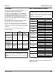
12. Operate the ice machine for one hour. Then, check
the pressure drop across the suction line filter-drier.
A. If the pressure drop is less than 1 psi, the filter-
drier should be adequate for complete cleanup.
B. If the pressure drop exceeds 1 psi, change the
suction line filter-drier and the liquid line drier.
Repeat until the pressure drop is acceptable.
13. Operate the ice machine for 48-72 hours. Then,
remove the suction line drier and change the liquid
line drier.
14. Follow normal evacuation procedures.
REPLACING PRESSURE CONTROLS WITHOUT
REMOVING REFRIGERANT CHARGE
This procedure reduces repair time and cost. Use it
when any of the following components require
replacement, and the refrigeration system is operational
and leak-free.
• Fan cycle control (air-cooled only)
• Water regulating valve (water-cooled only)
• High pressure cut-out control
• High side service valve
• Low side service valve
1. Disconnect power to the ice machine.
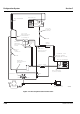
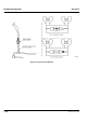
2. Follow all manufacturer’s instructions supplied with
the pinch-off tool. Position the pinch-off tool around
the tubing as far from the pressure control as
feasible. (See the figure on next page.) Clamp down
on the tubing until the pinch-off is complete.
3. Cut the tubing of the defective component with a
small tubing cutter.
4. Solder the replacement component in place. Allow
the solder joint to cool.
5. Remove the pinch-off tool.
6. Re-round the tubing. Position the flattened tubing in
the proper hole in the pinch off tool. Tighten the
wingnuts until the block is tight and the tubing is
rounded. (See the drawing on next page.)
NOTE: The pressure controls will operate normally once
the tubing is re-rounded. Tubing may not re-round
100%.
Important
Dry nitrogen is recommended for this procedure.
This will prevent CFC release.
Important
This is a required in-warranty repair procedure.
!
Warning
Do not unsolder a defective component. Cut it out of
the system. Do not remove the pinch-off tool until
the new component is securely in place.