
Service manual

Section 6 Electrical System
Part No. 80-1100-3 6-3
Wiring Diagram Sequence of
Operation
SELF-CONTAINED MODELS
Initial Start-Up or Start-Up After
Automatic Shut-Off
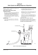
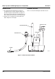
1. WATER PURGE
Before the compressor starts, the
water pump and water dump
solenoid are energized for 45
seconds to purge old water from the
ice machine. This ensures that the
ice-making cycle starts with fresh
water.
The harvest valve(s) is also
energized during the water purge. In
the case of an initial refrigeration
start-up, it stays on for an additional
5 seconds (50 seconds total).
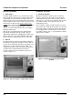
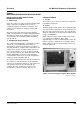
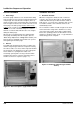
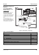
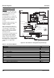
Figure 6-1. Self-Contained — Water Purge
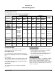
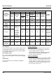
Table 6-1. Self-Contained Models
1. Water Purge (45 Seconds)
Toggle Switch ICE
Bin Switch Closed
Control Board Relays
#1 Water Pump Closed / ON
#2 Water Fill Valve Open / OFF
#3 Harvest Solenoid Closed / ON
#4 Water Dump Valve Closed / ON
#5 Contactor Coil Open / OFF
Compressor OFF
Condenser Fan Motor OFF
Safety Controls (Which could stop ice machine operation)
High Pressure Cut-Out Closed
Main Fuse (On Control Board) Closed
*OVERLOAD
FAN CYCLE CONTROL
BIN SWITCH
TB35
TB33
(52)
(51)
(48)
CONTACTOR
CONTACTS
L1
(42)
(66)
(64)
ICE THICKNESS PROBE
WATER LEVEL PROBE
NOT USED
T
B35
HIGH PRES
CUTOUT
TB32
L1
(55)
RUN CAPACITOR
RUN CAPACITOR**
C
S
R
TB34
(53)
(47)
(85) (86)
COMPRESSOR
FAN MOTOR
(AIR COOLED ONLY)
R
R
(45)
(46) (50)
PTCR
BIN SWITCH LIGHT
HARVEST LIGHT/
SAFETY LIMIT CODE LIGHT
CLEAN LIGHT
WATER LEVEL
(49)
(63)
(62)
(66)
(65)
(69)
ICE
OFF
CLEAN
(67)
(68)
1F
1C
LOW D.C.
VOLTAGE
PLUG
(62)
1G
TOGGLE SWITCH
68
67
69
66
62
VIEW FOR WIRING
INTERNAL WORKING
VIEW
TB37
(74)
(59)
(73)
(56)
CONTACTOR
COIL
TERMINATES AT
PIN CONNECTION
TB3
0
TB3
0
TB30
TB30
L2 (N)
SEE SERIAL PLATE FOR VOLTAGE
(58)
FUSE (7A)
TRANS.
2
4
1
3
5
(61)
(60)
TB31
(76)
(98)
(57)
(99)
(75)
HARVEST
SOLENOID
DUMP
SOLENOID
(81)
WATER
PUMP
(77)
(80)
(21)
(22)
WATER
VALVE
TB30
TB30
(20)
SV1646-1