Q Model Ice Machines Installation and Owner/Operator Use and Care Manual Thank you for selecting a Manitowoc Ice Machine, the dependability leader in ice making equipment and related products. With proper installation, care and maintenance, your new Manitowoc Ice Machine will provide you with many years of reliable and economical performance.
Safety Notices Procedural Notices As you work on a Q Series Ice Machine, be sure to pay close attention to the safety notices in this manual. Disregarding the notices may lead to serious injury and/ or damage to the ice machine. As you work on a Q Series Ice Machine, be sure to read the procedural notices in this manual. These notices supply helpful information which may assist you as you work.
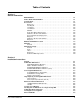
Table of Contents Section 1 General Information Model Numbers . . . . . . . . . . . . . . . . . . . . . . . . . . . . . . . . . . . . . . . . . . . . . . . . . . How to Read a Model Number . . . . . . . . . . . . . . . . . . . . . . . . . . . . . . . . . . . . . . Ice Cube Sizes . . . . . . . . . . . . . . . . . . . . . . . . . . . . . . . . . . . . . . . . . . . . . . . . . . . Accessories . . . . . . . . . . . . . . . . . . . . . . . . . . . . . . . . . . . . . . . . . . . . . . . . . . . . .
Table of Contents (continued) Electrical Service . . . . . . . . . . . . . . . . . . . . . . . . . . . . . . . . . . . . . . . . . . . . . . . . General . . . . . . . . . . . . . . . . . . . . . . . . . . . . . . . . . . . . . . . . . . . . . . . . . . . . . Voltage . . . . . . . . . . . . . . . . . . . . . . . . . . . . . . . . . . . . . . . . . . . . . . . . . . . . . Fuse/Circuit Breaker . . . . . . . . . . . . . . . . . . . . . . . . . . . . . . . . . . . . . . . . . . . Minimum Circuit Ampacity . . . .
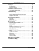
Table of Contents Section 3 Ice Machine Operation Component Identification . . . . . . . . . . . . . . . . . . . . . . . . . . . . . . . . . . . . . . . . . . Self-Contained Air- and Water-Cooled Q200/Q280/Q320/Q370/Q420/Q450/Q600/Q800/Q1000/Q1300/Q1600/Q1800 . Initial Start-Up or Start-Up After Automatic Shut-Off . . . . . . . . . . . . . . . . . . . Freeze Sequence . . . . . . . . . . . . . . . . . . . . . . . . . . . . . . . . . . . . . . . . . . . . . Harvest Sequence . . . . . . . . . . . . . . . . .
Table of Contents (continued) 4 Part Number 000001114
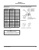
Section 1 General Information Model Numbers How to Read a Model Number This manual covers the following models: Self-Contained Air-Cooled QD0322A QY0324A QD0422A QY0424A QD0282A QY0284A QD0372A QY0374A QD0452A QY0454A QD0602A QY0604A QD0802A QY0804A QD1002A QY1004A QD1302A QY1304A --QD1802A QY1804A Self-Contained Water-Cooled QD0323W QY0325W QD0423W QY0425W QD0283W QY0285W QD0373W QY0375W QD0453W QY0455W QD0603W QY0605W QD0803W QY0805W QD1003W QY1005W QD1303W QY1305W QD1603W QY1605W QD1803W QY1805W Remo
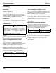
General Information Section 1 Accessories Contact your Manitowoc distributor for these optional accessories: BIN CASTER AUCS® AUTOMATIC CLEANING SYSTEM Replaces standard legs. This accessory reduces equipment cleaning expense. The AuCS® accessory monitors ice making cycles and initiates cleaning procedures automatically. STACKING KIT As your business grows and your ice needs increase, Manitowoc stack-on capability can double your daily ice production without using additional floor space.
Section 1 General Information Model/Serial Number Location Record the model and serial number of your ice machine and bin or dispenser in the space provided below. These numbers are required when requesting information from your local Manitowoc distributor, or Manitowoc Ice, Inc. The model and serial number are listed on the OWNER WARRANTY REGISTRATION CARD. They are also listed on the MODEL/SERIAL NUMBER DECAL affixed to the ice machine, remote condenser and storage bin.
General Information Section 1 Warranty EXCLUSIONS GENERAL The following items are not included in the ice machine’s warranty coverage: The packet containing this manual also includes warranty information. Warranty coverage begins the day your new ice machine is installed. Important Complete and mail the OWNER WARRANTY REGISTRATION CARD as soon as possible to validate the installation date.
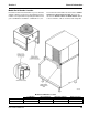
Section 2 Installation Instructions General Refer to Installation Manual for complete installation guidelines. Important Failure to follow these installation guidelines may affect warranty coverage. Ice Machine Dimensions Q320/Q370/Q420 ICE MACHINES WATER COOLED AIR COOLED SV1602 Ice Machine Q320 Q370 Q420 Part Number 000001114 SV1611 Dimension H 21.5 in (54.6 cm) 21.5 in (54.6 cm) 26.5 in (67.
Installation Instructions Section 2 Q280 – Q1000 ICE MACHINES Q1300/Q1600/Q1800 ICE MACHINES WATER-COOLED SELF CONTAINED AIR-COOLED SV1612 AIR-COOLED SV1628 SELF CONTAINED WATER-COOLED SV1613 Ice Machine Q200 – Q280 Q450 Q600 Q800 Q1000 2-2 Dimension H 16.5 in (41.9 cm) 21.5 in (54.6 cm) 21.5 in (54.6 cm) 26.5 in (67.3 cm) 29.5 in (74.9 cm) SV1627 Ice Machine Q1300/Q1600 Q1800 Dimension H 29.5 in (74.9 cm) 29.5 in (74.
Section 2 Installation Instructions Q1300/Q1600/Q1800 ICE MACHINES (CONT.) S320/S420 ICE STORAGE BINS REMOTE AIR-COOLED SV1614 SV1629 Bin Model S320 S420 Dimension A 34.0 in (86.3 cm) 34.0 in (86.3 cm) Dimension B 32.0 in (81.3 cm) 44.0 in (111.7 cm) Ice Storage Bin Dimensions S170/S400/S570 ICE STORAGE BINS S970 ICE STORAGE BINS SV1609 SV1610 Bin Model S170 S400 S570 Dimension A 29.5 in (74.9 cm) 34.0 in (86.3 cm) 34.0 in (86.3 cm) Part Number 000001114 Dimension B 19.1 in (48.5 cm) 32.
Installation Instructions Section 2 Large Capacity Ice Storage Bin Dimensions 30 INCH (76 CM) ! Warning A 34” (86.4 cm) B All Manitowoc ice machines require the ice storage system (bin, dispenser, etc.) to incorporate an ice deflector. The Q1300, Q1600, Q1800 ice machines require adding Manitowoc Ice Deflector Kit K00139 when installing with non-Manitowoc ice storage systems.
Section 2 Installation Instructions Remote Condenser Dimensions JC0495/JC0895/JC1095/JC1395 SV1297 JC1895 SV1301 Part Number 000001114 2-5
Installation Instructions Section 2 Location of Ice Machine The location selected for the ice machine must meet the following criteria. If any of these criteria are not met, select another location. • The location must be free of airborne and other contaminants. • The air temperature must be at least 35°F (1.6°C), but must not exceed 110°F (43.4°C). • The location must not be near heat-generating equipment or in direct sunlight.
Section 2 Installation Instructions Leveling the Ice Storage Bin Air-Cooled Baffle 1. Screw the leveling legs onto the bottom of the bin. 2. Screw the foot of each leg in as far as possible. The air-cooled baffle prevents condenser air from recirculating. To install: 1. Remove the back panel screws next to the condenser. ! Caution The legs must be screwed in tightly to prevent them from bending. 2. Align the mounting holes in the air baffle with the screw holes and reinstall the screws. 3.
Installation Instructions Section 2 Electrical Service FUSE/CIRCUIT BREAKER GENERAL A separate fuse/circuit breaker must be provided for each ice machine. Circuit breakers must be H.A.C.R. rated (does not apply in Canada). ! Warning All wiring must conform to local, state and national codes. MINIMUM CIRCUIT AMPACITY VOLTAGE The minimum circuit ampacity is used to help select the wire size of the electrical supply. (Minimum circuit ampacity is not the ice machine’s running amp load.
Section 2 Installation Instructions Q320/370/420 Ice Machines Voltage Phase Cycle Ice Machine Q320 Q370 Q420 115/1/60 208-230/1/60 230/1/50 115/1/60 208-230/1/60 230/1/50 115/1/60 208-230/1/60 230/1/50 Air-Cooled Maximum Fuse/ Minimum Circuit Breaker Circuit Amps 15 11.2 15 4.8 15 5.2 20 12.9 15 6.2 15 6.2 20 12.3 15 7.8 15 6.3 Water Cooled Maximum Fuse/ Minimum Circuit Breaker Circuit Amps 15 10.5 15 4.2 15 4.7 20 12.2 15 5.8 15 5.8 20 11.4 15 7.4 15 5.
Installation Instructions Section 2 Self-Contained Electrical Wiring Connections ! Warning These diagrams are not intended to show proper wire routing, wire sizing, disconnects, etc., only the correct wire connections. SELF CONTAINED ICE MACHINE 208-230/3/60 All electrical work, including wire routing and grounding, must conform to local, state and national electrical codes. Though wire nuts are shown in the drawings, the ice machine field wiring connections may use either wire nuts or screw terminals.
Section 2 Installation Instructions Remote Electrical Wiring Connections REMOTE ICE MACHINE WITH SINGLE CIRCUIT MODEL CONDENSER 208-230/3/60 OR 380-415/3/50 ! Warning These diagrams are not intended to show proper wire routing, wire sizing, disconnects, etc., only the correct wire connections. All electrical work, including wire routing and grounding, must conform to local, state and national electrical codes.
Installation Instructions Section 2 Water Supply and Drain Requirements DRAIN CONNECTIONS WATER SUPPLY Follow these guidelines when installing drain lines to prevent drain water from flowing back into the ice machine and storage bin: Local water conditions may require treatment of the water to inhibit scale formation, filter sediment, and remove chlorine odor and taste.
Section 2 Installation Instructions WATER SUPPLY AND DRAIN LINE SIZING/CONNECTIONS ! Caution Plumbing must conform to state and local codes. Location Water Temperature Water Pressure Ice Machine Fitting Ice Making Water Inlet 33°F (0.6°C) Min. 90°F (32.2°C) Max. 20 psi (137.9 kPA) Min. 80 psi (551.5 kPA) Max. 3/8" Female Pipe Thread Ice Making Water Drain --- --- Condenser Water Inlet 33°F (0.6°C) Min. 90°F (32.2°C) Max. 20 psi (137.9 kPA) Min. 150 psi (1034.2 kPA) Max.
Installation Instructions Section 2 Remote Condenser/Line Set Installation Ice Machine Q490 Q690 Q890 Q1090 Q1390 Q1690 Q1890 Remote Single Circuit Condenser JC0495 JC0895 Line Set* RT-20-R404A RT-35-R404A RT-50-R404A JC1095 JC1395 JC1695 JC1895 RL-20-R404A RL-35-R404A RL-50-R404A Discharge Line 1/2" (12.7 mm) 1/2" (12.7 mm) Liquid Line 5/16" (7.9 mm) 3/8" (9.5 mm) sets of up to 50' (15.25 m). The serial tag on the ice machine indicates the refrigerant charge.
Section 2 Installation Instructions GENERAL GUIDELINES FOR ROUTING LINE SETS Condensers must be mounted horizontally with the fan motor on top. First, cut a 2.5" (63.5 mm) circular hole in the wall or roof for tubing routing. The line set end with the 90° bend will connect to the ice machine. The straight end will connect to the remote condenser. Remote condenser installations consist of vertical and horizontal line sets between the ice machine and the condenser.
Installation Instructions Section 2 Make the following calculations to make sure the line set layout is within specifications. CALCULATING REMOTE CONDENSER INSTALLATION DISTANCES Line Set Length 1. Insert the measured rise into the formula below. Multiply by 1.7 to get the calculated rise. (Example: A condenser located 10 feet above the ice machine has a calculated rise of 17 feet.) The maximum length is 100' (30.5 m). The ice machine compressor must have the proper oil return.
Section 2 Installation Instructions LENGTHENING OR REDUCING LINE SET LENGTHS REMOTE RECEIVER SERVICE VALVE In most cases, by routing the line set properly, shortening will not be necessary. When shortening or lengthening is required, do so before connecting the line set to the ice machine or the remote condenser. This prevents the loss of refrigerant in the ice machine or condenser. The receiver service valve is closed during shipment. Open the valve prior to starting the ice machine.
Installation Instructions Section 2 Remote Ice Machine Usage with Non-Manitowoc Multi-Circuit Condensers WARRANTY FAN MOTOR The sixty (60) month compressor warranty, including thirty six (36) month labor replacement warranty, shall not apply when the remote ice machine is not installed within the remote specifications. The foregoing warranty shall not apply to any ice machine installed and/or maintained inconsistent with the technical instructions provided by Manitowoc Ice, Inc.
Section 2 Installation Instructions NON-MANITOWOC MULTI-CIRCUIT CONDENSER SIZING CHART Ice Machine Model Refrigerant Heat of Rejection Internal Condenser Volume (cu ft) Peak Btu/hr 9,600 13,900 Min Max 6 lbs. 8 lbs. Average Btu/hr 7,000 9,000 0.020 0.045 0.035 0.060 8 lbs. 9.5 lbs. 14 lbs.1 17 lbs.1 17 lbs.1 18 lbs.1 12,400 16,000 24,000 24,000 36,000 24,000 19,500 24,700 35,500 35,500 50,000 36,000 0.045 0.065 0.085 0.130 0.130 0.130 0.060 0.085 0.105 0.170 0.170 0.
Installation Instructions Installation Check List Section 2 Are the ice machine and bin drains vented? Is the Ice Machine level? Has all of the internal packing been removed? Are all electrical leads free from contact with refrigeration lines and moving equipment? Have all of the electrical and water connections been made? Has the owner/operator been instructed regarding maintenance and the use of Manitowoc Cleaner and Sanitizer? Has the supply voltage been tested and checked against the rating on the
Section 2 Installation Instructions Before Starting the Ice Machine AuCS® Automatic Cleaning System All Manitowoc ice machines are factory-operated and adjusted before shipment. Normally, new installations do not require any adjustment. To ensure proper operation, follow the Operational Checks in Section 3 of this manual. Starting the ice machine and completing the Operational Checks are the responsibilities of the owner/operator.
Installation Instructions Section 2 THIS PAGE INTENTIONALLY LEFT BLANK 2-22 Part Number 000001114
Section 3 Ice Machine Operation Component Identification AIR CONDENSER HARVEST VALVE CONDENSER WATER REGULATING VALVE REMOTE COUPLINGS WATER DUMP VALVE COMPRESSOR WATER CONDENSER DRAIN HOSE DISTRIBUTION TUBE ICE THICKNESS PROBE EVAPORATOR WATER COOLED MODEL SV1604G HIGH PRESSURE CUTOUT/ MANUAL RESET (When applicable) ICE/OFF/CLEAN SWITCH WATER PUMP WATER CURTAIN WATER TROUGH SV1605 BIN SWITCH Figure 3-1.
Ice Machine Operation Section 3 Self-Contained Air- and Water-Cooled Q200/Q280/Q320/Q370/Q420/Q450/Q600/Q800/Q1000/Q1300/Q1600/Q1800 INITIAL START-UP OR START-UP AFTER AUTOMATIC SHUT-OFF 1. Water Purge Before the compressor starts, the water pump and water dump solenoid are energized for 45 seconds, to completely purge the ice machine of old water. This feature ensures that the ice making cycle starts with fresh water.
Section 3 Ice Machine Operation HARVEST SEQUENCE AUTOMATIC SHUT-OFF 5. Water Purge 7. Automatic Shut-Off The water pump continues to run, and the water dump valve energizes for 45 seconds to purge the water in the sump trough. The water fill valve energizes (turns on) and de-energizes (turns off) strictly by time. The water fill valve energizes for the last 15 seconds of the 45-second water purge.
Ice Machine Operation Section 3 Remote Q450/Q600/Q800/Q1000/Q1300/Q1600/Q1800 INITIAL START-UP OR START-UP AFTER AUTOMATIC SHUT-OFF 1. Water Purge Before the compressor starts, the water pump and water dump solenoid are energized for 45 seconds, to completely purge the ice machine of old water. This feature ensures that the ice making cycle starts with fresh water.
Section 3 Ice Machine Operation HARVEST SEQUENCE AUTOMATIC SHUT-OFF 5. Water Purge 7. Automatic Shut-Off The water pump continues to run, and the water dump valve energizes for 45 seconds to purge the water in the sump trough. The water fill valve energizes (turns on) and de-energizes (turns off) strictly by time. The water fill valve energizes for the last 15 seconds of the 45-second water purge.
Ice Machine Operation Section 3 Operational Checks ICE THICKNESS CHECK GENERAL The ice thickness probe is factory-set to maintain the ice bridge thickness at 1/8" (3.2 mm). Manitowoc ice machines are factory-operated and adjusted before shipment. Normally, new installations do not require any adjustment.
Section 3 Ice Machine Operation HARVEST SEQUENCE WATER PURGE The harvest sequence water purge adjustment may be used when the ice machine is hooked up to special water systems, such as a de-ionized water treatment system. Important The harvest sequence water purge is factory-set at 45 seconds. A shorter purge setting (with standard water supplies such as city water) is not recommended. This can increase water system cleaning and sanitizing requirements.
Ice Machine Operation Section 3 THIS PAGE INTENTIONALLY LEFT BLANK 3-8 Part Number 000001114
Section 4 Maintenance Section 4 Maintenance Interior Cleaning and Sanitizing GENERAL Step 3 Remove all ice from the bin. Clean and sanitize the ice machine every six months for efficient operation. If the ice machine requires more frequent cleaning and sanitizing, consult a qualified service company to test the water quality and recommend appropriate water treatment. The ice machine must be taken apart for cleaning and sanitizing. Step 4 Place the toggle switch in the CLEAN position.
Maintenance Section 4 C. Remove the water distribution tube B. Remove the ice thickness probe • • Compress the hinge pin on the top of the ice thickness probe. Disconnect the water hose from the distribution tube. 2 3 1. LIFT UP 2. SLIDE BACK 3. SLIDE TO RIGHT 1 DISTRIBUTION TUBE COMPRESS HINGE PIN TO REMOVE THUMBSCREW LOCATING PIN THUMBSCREW SV1620 Water Distribution Tube Removal SV3135 Ice Thickness Probe Removal • • Loosen the two thumbscrews which secure the distribution tube.
Section 4 Maintenance D. Remove the white vinyl water distribution tubing • Disconnect the hose from the water pump outlet. • Disconnect the hose from the dump valve (the tubing pressure fits - pull tubing into evaporator compartment). F. Remove the water level probe • Loosen the screw that holds the water level probe in place. The probe can easily be cleaned and sanitized at this point without proceeding to step 2.
Maintenance Section 4 Step 9 While components are soaking, use 1/2 of the cleaner/water solution to clean all foodzone surfaces of the ice machine and bin (or dispenser).
Section 4 Maintenance Step 16 The ice machine will stop after the sanitize cycle (approximately 30 minutes). Place the toggle switch in the OFF position and disconnect power to the ice machine. ! Warning Disconnect the electric power to the ice machine at the electric service switch box.. Step 17 Repeat step 6 for hand sanitizing. Step 18 Mix a solution of sanitizer and warm water. Solution Type Sanitizer Water 6 gal.
Maintenance Section 4 ADDITIONAL COMPONENT REMOVAL The following components may be removed for easier access in some installations or they may need to be removed and cleaned to correct an operational problem. Water Inlet Valve The water inlet valve normally does not require removal for cleaning. Refer to Section 5 for a list of causes for “No Water Entering Water Trough” or “Water Overflows Water Trough. 1.
Section 4 Maintenance COIL SPRING PLUNGER NYLON GASKET DIAPHRAM MOUNTING BRACKET VALVE BODY Dump Valve Disassembly Part Number 000001114 4-7
Maintenance Section 4 Ice Machine Inspection Cleaning the Condenser Check all water fittings and lines for leaks. Also, make sure the refrigeration tubing is not rubbing or vibrating against other tubing, panels, etc. GENERAL Do not put anything (boxes, etc.) on the sides or back of the ice machine. There must be adequate airflow through and around the ice machine to maximize ice production and ensure long component life.
Section 4 Maintenance 4. Straighten any bent condenser fins with a fin comb. “COMB” DOWN ONLY Water-Cooled Condenser and Water Regulating Valve Symptoms of restrictions in the condenser water circuit include: • Low ice production • High water consumption • High operating temperatures • High operating pressures CONDENSER If the ice machine is experiencing any of these symptoms, the water-cooled condenser and water regulating valve may require cleaning due to scale build-up.
Maintenance Section 4 Removal from Service/Winterization GENERAL Special precautions must be taken if the ice machine is to be removed from service for an extended period of time or exposed to ambient temperatures of 32°F (0°C) or below. ! Caution WATER-COOLED ICE MACHINES 1. Perform steps 1-6 under “Self-Contained Air-Cooled Ice Machines.” 2. Disconnect the incoming water and drain lines from the water-cooled condenser. 3.
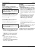
Section 5 Before Calling for Service Checklist If a problem arises during operation of your ice machine, follow the checklist below before calling service. Routine adjustments and maintenance procedures are not covered by the warranty. Problem Ice machine does not operate. Ice machine stops, and can be restarted by moving the toggle switch to OFF and back to ICE. Ice machine does not release ice or is slow to harvest. Ice machine does not cycle into harvest mode.
Before Calling for Service Problem Ice machine produces shallow or incomplete cubes, or the ice fill pattern on the evaporator is incomplete. Section 5 Possible Cause Ice thickness probe is out of adjustment. Water trough level is too high or too low. Water inlet valve filter screen is dirty. Water filtration is poor. Hot incoming water. Water inlet valve is not working. Incorrect incoming water pressure. Ice machine head section is not level. Low ice capacity. Water inlet valve filter screen is dirty.
Section 5 Before Calling for Service THIS PAGE INTENTIONALLY LEFT BLANK Part Number 000001114 5-3
Before Calling for Service Section 5 THIS PAGE INTENTIONALLY LEFT BLANK 5-4 Part Number 000001114
Manitowoc Ice, Inc. 2110 South 26th Street P.O. Box 1720 Manitowoc, WI 54221-1720 Phone: (920) 682-0161 Service Fax: (920) 683-7585 Web Site - www.manitowocice.com Manitowoc Foodservice International S.A.S. 18 Chemin de Charbonnières F-69132 Ecully Cedex Téléphone : +33 (0)4 72 18 22 50 Fax : +33 (0)4 72 18 22 60 Site Web – www.manitowocice.com Manitowoc (China) International Refrigeration Company, LTD No. 151 Jiam Ye Road Hangzhou Hi-Tech Industry Development Zone (Bin Jiang) Hangzhou, Zhejiang 310052 P.