
Service Manual
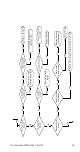
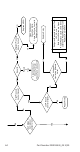
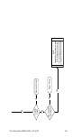
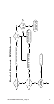
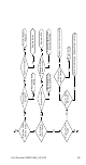
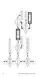
Table Of Contents
- General Information
- Model Numbers
- Installation
- Maintenance
- Sequence of Operation
- Troubleshooting
- Component Specifications
- Charts
- Diagrams
- Wiring Diagrams
- Flake Models
- Nugget Models
- Condensing Units
- Compressor Start Component Wiring
- Refrigeration Tubing Schematics
- UFF0200/UFF0350/UNF0200/UNF0300
- RFF0320/RNF0320 Air-cooled
- RFF0620/RNF0620/RNF1100 Air & Water-cooled
- RNF1020C QuietQube Head Section & RCUF1000 Condensing Unit
- RFF1220C & RCUF1000 Condensing Unit
- RNF2000C QuietQube Head Section & RCUF2200 Condensing Unit
- RFF2200C QuietQube Head Section & RCUF2200 Condensing Unit
- RFF1300 Air & Water-cooled
- RFF2500 Air-cooled

66 Part Number 000015433_03 5/20
RFF2500 Troubleshooting
SELF-CONTAINED AIR-COOLED
Normal Operation
When the toggle switch is placed in the ON position the
following controls must be in the closed position before
the ice machine will start:
A. Bin Thermostat
B. High Pressure Cut-out Switch
C. Ice Chute Safety Switch
D. Low Pressure Switch
E. Low Water Level Switch
Placing the toggle switch in the ON position starts the
gear motor. After 8 minutes of correct rotation the time
delay ends and the compressor starts. The ice machine will
continue to make ice until ice contacts the bin thermostat.
The ice machine remains off until ice no longer contacts
the bin thermostat.
ROTATION SENSOR OPERATION
Light Definition
Yellow Blinking Time Delay Period
Yellow Solid Normal Operation Sensing
Red Blinking Fault Time Delay Period
Red Solid Lockout - 8 Consecutive Faults
Remove/Restore Power To Reset
See “Rotation Sensor” on page 85 for sequence of operation