S1800M Model Ice Machines Installation Use and Care Manual Thank you for selecting a Manitowoc Ice Machine, the dependability leader in ice making equipment and related products. With proper installation, care and maintenance, your new Manitowoc Ice Machine will provide you with many years of reliable and economical performance. This manual is updated as new information and models are released. Visit our website for the latest manual. www.manitowocice.
Safety Notices Procedural Notices As you work on an S Model Series Ice Machine, be sure to pay close attention to the safety notices in this manual. Disregarding the notices may lead to serious injury and/or damage to the ice machine. As you work on an S Model Series Ice Machine, be sure to read the procedural notices in this manual. These notices supply helpful information which may assist you as you work.
Table of Contents Section 1 General Information Model Numbers . . . . . . . . . . . . . . . . . . . . . . . . . . . . . . . . . . . . . . . . . . . . . . . . . How to Read a Model Number . . . . . . . . . . . . . . . . . . . . . . . . . . . . . . . . . . . . . Ice Cube Sizes . . . . . . . . . . . . . . . . . . . . . . . . . . . . . . . . . . . . . . . . . . . . . . . . . . Accessories . . . . . . . . . . . . . . . . . . . . . . . . . . . . . . . . . . . . . . . . . . . . . . . . . . . . Bin Caster . . . . .
Table of Contents (continued) Section 3 Ice Machine Operation Component Identification . . . . . . . . . . . . . . . . . . . . . . . . . . . . . . . . . . . . . . . . . Sequence Of Operation . . . . . . . . . . . . . . . . . . . . . . . . . . . . . . . . . . . . . . . . . . . Initial Start-Up or Start-Up After Automatic Shut-Off . . . . . . . . . . . . . . . . . . Freeze Sequence . . . . . . . . . . . . . . . . . . . . . . . . . . . . . . . . . . . . . . . . . . . . Harvest Sequence . . . . . . . . . . . .
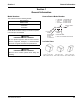
Section 1 General Information Section 1 General Information Model Numbers How to Read a Model Number This manual covers the following models: # CUBE SIZE Self-Contained Water-Cooled SR1801WM SD1803WM SY1805WM NOTE: Model numbers ending in 3 indicate a 3-phase unit. Example: SY1805WM3 ! Warning PERSONAL INJURY POTENTIAL Do not operate equipment that has been misused, abused, neglected, damaged, or altered/modified from that of original manufactured specifications.
General Information Section 1 Accessories MANITOWOC CLEANER AND SANITIZER Contact your Manitowoc distributor for these optional accessories: Manitowoc Ice Machine Cleaner and Sanitizer are available in convenient 16 oz. (473 ml) bottles. These are the only cleaner and sanitizer approved for use with Manitowoc products. BIN CASTER Replaces standard legs. ICE BAGGER Maximize profits from bagged ice sales with this convenient accessory.
Section 1 General Information Model/Serial Number Location These numbers are required when requesting information from your local Manitowoc distributor, or Manitowoc Ice, Inc. The model and serial number are listed on the MODEL/ SERIAL NUMBER DECAL affixed to the ice machine, remote condenser and storage bin.
General Information Section 1 Owner Warranty Registration Card GENERAL EXCLUSIONS The packet containing this manual also includes warranty information. Warranty coverage begins the day your new ice machine is installed. The following items are not included in the ice machine’s warranty coverage: Important Complete and mail the OWNER WARRANTY REGISTARATION CARD as soon as possible to validate the installation date.
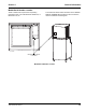
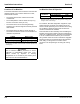
Section 2 Installation Instructions Section 2 Installation Instructions General These instructions are provided to assist the qualified installer. Check your local Yellow Pages for the name of the nearest Manitowoc distributor, or call Manitowoc Ice, Inc. for information regarding start-up services. Important Failure to follow these installation guidelines may affect warranty coverage. Ice Machine Dimensions S1800 WATER-COOLED ICE MACHINES 2.50" (6.35cm) ELECTRICAL H A B C 11.0" (27.9cm) E 2.
Installation Instructions Section 2 Location of Ice Machine Ice Machine Heat of Rejection The location selected for the ice machine must meet the following criteria. If any of these criteria are not met, select another location. • The location must be free of airborne and other contaminants. • The air temperature must be at least 35°F (1.6°C), but must not exceed 110°F (43.4°C). • The location must not be near heat-generating equipment or in direct sunlight and must be protected from weather.
Section 2 Installation Instructions Electrical Service Important GENERAL Observe correct polarity of incoming line voltage. ! Warning All wiring must conform to local, state and national codes. VOLTAGE The maximum allowable voltage variation is ±10% of the rated voltage at ice machine start-up (when the electrical load is highest). ! Warning The ice machine must be grounded in accordance with national and local electrical codes.
Installation Instructions Section 2 Self-Contained Electrical Wiring Connections ! Warning These diagrams are not intended to show proper wire routing, wire sizing, disconnects, etc., only the correct wire connections. SELF CONTAINED ICE MACHINE 208-230/3/60 All electrical work, including wire routing and grounding, must conform to local, state and national electrical codes. Though wire nuts are shown in the drawings, the ice machine field wiring connections may use either wire nuts or screw terminals.
Section 2 Installation Instructions Water Supply and Drain Requirements DRAIN CONNECTIONS WATER SUPPLY Follow these guidelines when installing drain lines to prevent drain water from flowing back into the ice machine and storage bin: Local water conditions may require treatment of the water to inhibit scale formation, filter sediment, and remove chlorine odor and taste.
Installation Instructions Section 2 WATER SUPPLY AND DRAIN LINE SIZING/CONNECTIONS ! Caution Plumbing must conform to state and local codes. Location Water Temperature Water Pressure Ice Machine Fitting Ice Making Water Inlet 35°F (1.6°C) Min. 90°F (32.2°C) Max. 20 psi (137.9 kPA) Min. 80 psi (551.5 kPA) Max. 3/8" Female Pipe Thread Tubing Size Up to Ice Machine Fitting 3/8" (.95 cm) minimum inside diameter Ice Making Water Drain --- --- 1/2" Female Pipe Thread 1/2" (1.
Section 2 Installation Instructions Installation Check List F F F F F F F F F Is the Ice Machine level? Has all of the internal packing been removed? Have all of the electrical and water connections been made? F F F Has the supply voltage been tested and checked against the rating on the nameplate? F Is there proper clearance around the ice machine for air circulation? F Has the ice machine been installed where ambient temperatures will remain in the range of 35° - 110°F (1.6° - 43.
Installation Instructions Section 2 Before Starting the Ice Machine AuCS® Automatic Cleaning System All Manitowoc ice machines are factory-operated and adjusted before shipment. Normally, new installations do not require any adjustment. This optional accessory monitors ice making cycles and initiates cleaning procedures automatically. The AuCS® accessory can be set to automatically clean or sanitize the ice machine every 2, 4 or 12 weeks.
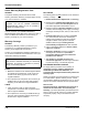
Section 3 Ice Machine Operation Section 3 Ice Machine Operation Component Identification Water Distribution Tube Toggle Switch Water Curtain Dump Valve Check Valve sv3149 Ice Thickness Probe Bin Switch Water Level Probe Water Pump Water Inlet Location Water Inlet Valve (Located in Refrigeration Compartment) sv3150 Part Number 80-1633-3 3-1
Ice Machine Operation Section 3 Sequence Of Operation NOTE: The toggle switch must be in the ice position and the water curtain must be in place on the evaporator before the ice machine will start. INITIAL START-UP OR START-UP AFTER AUTOMATIC SHUT-OFF 1. Water Purge Before the compressor starts, the water pump and water dump solenoid are energized for 45 seconds, to completely purge the ice machine of old water. This feature ensures that the ice making cycle starts with fresh water.
Section 3 Ice Machine Operation HARVEST SEQUENCE SAFETY TIMERS 5. Water Purge The control board has the following non-adjustable safety timers: The harvest valve(s) opens at the beginning of the water purge to divert hot refrigerant gas into the evaporator. The water pump continues to run, and the water dump valve energizes for 45 seconds to purge the water in the sump trough. The water fill valve energizes (turns on) and de-energizes (turns off) strictly by time.
Ice Machine Operation Section 3 Operational Checks ICE THICKNESS CHECK GENERAL The ice thickness probe is factory-set to maintain the ice bridge thickness at 1/8" (.32 cm). Manitowoc ice machines are factory-operated and adjusted before shipment. Normally, new installations do not require any adjustment.
Section 3 Ice Machine Operation HARVEST SEQUENCE WATER PURGE The harvest sequence water purge adjustment may be used when the ice machine is hooked up to special water systems, such as a de-ionized water treatment system. ! Warning • During the harvest sequence water purge, the water fill valve energizes and de-energizes by time. The water purge must be at the factory setting of 45 seconds for the water fill valve to energize during the last 15 seconds of the water purge.
Ice Machine Operation Section 3 THIS PAGE INTENTIONALLY LEFT BLANK 3-6 Part Number 80-1633-3
Section 4 Maintenance Section 4 Maintenance General You are responsible for maintaining the ice machine in accordance with the instructions in this manual. Maintenance procedures are not covered by the warranty. ! Warning If you do not understand the procedures or the safety precautions that must be followed, call your local Manitowoc service representative to perform the maintenance procedures for you.
Maintenance Section 4 Guardian™ Slime is a leading cause of ice machine breakdowns and biological growth is a health concern. The Guardian™ system releases chlorine dioxide on a controlled basis to inhibit the growth of bacteria and fungi that form slime and cause malodors in the food zone of ice machines. The Guardian™ will not control mineral or other water borne buildup. Your water quality will determine the length of time before mineral buildup affects ice machine performance.
Section 4 Maintenance Interior Cleaning and Sanitizing GENERAL Clean and sanitize the ice machine every six months for efficient operation. If the ice machine requires more frequent cleaning and sanitizing, consult a qualified service company to test the water quality and recommend appropriate water treatment. An extremely dirty ice machine must be taken apart for cleaning and sanitizing.
Maintenance Section 4 SANITIZING PROCEDURE Use sanitizer to remove algae or slime. Do not use it to remove lime scale or other mineral deposits. Step 1 Set the toggle switch to the OFF position after ice falls from the evaporator at the end of a Harvest cycle. Or, set the switch to the OFF position and allow the ice to melt off the evaporator. ! Caution Never use anything to force ice from the evaporator. Damage may result.
Section 4 Maintenance REMOVAL OF PARTS FOR CLEANING/SANITIZING 1. Turn off the electrical and water supply to the ice machine (and dispenser when applicable). 5. Use a soft-bristle brush or sponge (NOT a wire brush) to carefully clean the parts. ! Caution ! Warning Disconnect electric power to the ice machine (and dispenser if applicable) at the electric switch box before proceeding. ! Caution 2. Remove all ice from the bin. 3. Remove the water curtain and the components you want to clean or sanitize.
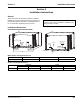
Maintenance Section 4 2. Ice Thickness Probe 1. Water Curtain A. Gently flex the curtain in the center and remove it from the right side. A. Compress the hinge pin on the top of the ice thickness probe. B. Slide the left pin out. STEP 1 STEP 2 COMPRESS HINGE PIN TO REMOVE SV3153 SV3135 Water Curtain Removal Ice Thickness Probe Removal B. Pivot the ice thickness probe to disengage one pin then the other. The ice thickness probe can be cleaned at this point without complete removal.
Section 4 Maintenance 3. Water Distribution Tube ! Warning Removing the distribution tube while the water pump is running will allow water to spray from ice machine. Disconnect the electrical power to the ice machine and dispenser at the electric service switch box and turn off the water supply. 4. Water Trough A. Depress tabs on right and left side of the water trough. B. Allow front of water trough to drop as you pull forward to disengage the rear pins.
Maintenance Section 4 Water Pump Water Level Probe 1. Remove the water trough. ! Warning ! Warning Disconnect the electrical power to the ice machine at the electrical disconnect before proceeding. 2. The water level probe normally does not require removal for cleaning. The probe can be wiped and cleaned in place or proceed to step 3. 3. Pull the water level probe straight down to disengage.
Section 4 Maintenance Water Dump Valve The water dump valve normally does not require removal for cleaning. To determine if removal is necessary: 1. Locate the water dump valve. 2. Set the toggle switch to ICE. 3. While the ice machine is in the freeze mode, check the dump valve’s clear plastic outlet drain hose for leakage. Important The plunger and the inside of the enclosing tube must be completely dry before assembly.
Maintenance Evaporator Tray Removal 1. Remove the water trough. 2. Remove thumbscrew on left side of tray. 3. Allow left side of tray to drop as you pull the tray to the left side. Continue until the outlet tube disengages from the right side. Section 4 Drain Line Check Valve The drain line check valve normally does not require removal for cleaning. Water loss from the sump trough will indicate removal and cleaning are required. sv3154 1. Remove check valve and tube assembly. A.
Section 4 Maintenance Water Inlet Valve The water inlet valve normally does not require removal for cleaning. Refer to Section 5 for a list of causes for “No Water Entering Water Trough” or “Water Overflows Water Trough. 1. When the ice machine is off, the water inlet valve must completely stop water flow into the machine. 2. When the ice machine is on, the water inlet valve must allow the proper water flow through it. Set the toggle switch to ON. Watch for water flow into the ice machine.
Maintenance Section 4 Removal from Service/Winterization GENERAL Special precautions must be taken if the ice machine is to be removed from service for an extended period of time or exposed to ambient temperatures of 32°F (0°C) or below. ! Caution If water is allowed to remain in the ice machine in freezing temperatures, severe damage to some components could result. Damage of this nature is not covered by the warranty. Follow the applicable procedure below. SELF-CONTAINED WATER-COOLED ICE MACHINES 1.
Section 5 Before Calling For Service Section 5 Before Calling For Service Checklist If a problem arises during operation of your ice machine, follow the checklist below before calling service. Routine adjustments and maintenance procedures are not covered by the warranty. Problem Ice machine does not operate. Possible Cause No electrical power to the ice machine and/or condensing unit. High pressure cutout tripping. ICE/OFF/CLEAN toggle switch set improperly. Water curtain stuck open.
Before Calling For Service Problem Ice machine produces shallow or incomplete cubes, or the ice fill pattern on the evaporator is incomplete. Section 5 Possible Cause Ice thickness probe is out of adjustment. Water trough level is too low. Water inlet valve filter screen is dirty. Water filtration is poor. Hot incoming water. Water inlet valve is not working. Incorrect incoming water pressure. Ice machine is not level. Low ice capacity. Water inlet valve filter screen is dirty.
MANITOWOC ICE, INC. 2110 South 26th Street P.O. Box 1720 Manitowoc, WI 54221-1720 Phone: (920) 682-0161 Service Fax: (920) 683-7585 Web Site - www.manitowocice.com © 2005 Manitowoc Ice, Inc. Litho in U.S.A.