
Service Manual
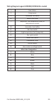
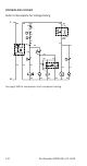
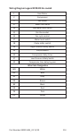
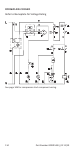
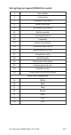
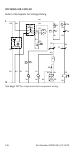

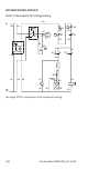
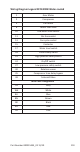
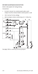
Table Of Contents
- General Information
- Model Numbers
- Installation
- Maintenance
- Sequence of Operation
- Troubleshooting
- Component Specifications
- Charts
- Diagrams

Part Number 000015433_02 11/19 115
Wiring Diagram Legend RFF0620 Air-cooled
1 Gear Motor
2 Compressor
4 Condenser fan motor
6 Water inlet valve
10 Low water level safety
11 Bin thermostat
13 Fan cycle control
15 Contactor
17 Water level switch
18 Ice chute safety switch
19 High pressure cut out
21 Compressor relay
24 On/Off switch
25 Compressor time delay
27 Low pressure cut out
30 Rotation sensor
35 Compressor time delay by-pass
Wire Color Designation
B White
BL Blue
G Grey
M Brown
N Black
R Red
RS Pink