
Service Manual
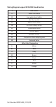
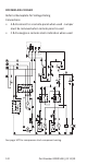
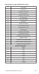
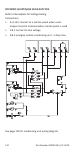
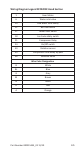

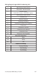
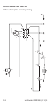

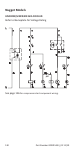
Table Of Contents
- General Information
- Model Numbers
- Installation
- Maintenance
- Sequence of Operation
- Troubleshooting
- Component Specifications
- Charts
- Diagrams

Part Number 000015433_02 11/19 121
Wiring Diagram Legend RFF1220C Head Section
1 Gear Motor
6 Water inlet valve
10 Low water level safety
11 Bin thermostat
17 Water level switch
18 Ice chute safety switch
21 Compressor Relay
24 On/Off switch
30 Rotation sensor
35 Compressor time delay by-pass
38 Solenoid Valve
Wire Color Designation
B White
BL Blue
G Grey
M Brown
N Black
R Red
V Violet
A Orange