
Owner`s manual
10
TECHNICAL DETAILS
CHANNELS: The Combi (XLR / 1/4") jack is wired to provide a 2400 ohm load for XLR sources
like mics, and 82K ohms for 1/4" plugs either balanced or unbalanced. On MIC VERSIONS
Phantom power can be injected with the back panel switches and uses a pair of traditional 6K8
resistors. Also on MIC VERSIONS, the signal is optionally phase reversed with a relay. On all
versions, the next stage is a very low noise instrumentation amp / DC servo. For those into numbers,
noise is rated at 1nV/÷ Hz, THD+N at .0009%, and it cleanly accepts +30 dBu signals. Similar
circuits have been used on the most expensive consoles, dedicated mic pres and high end A to D
converters, but not this many channels at this price. On MIC VERSIONS, this signal is sent to a line
driver, the INSERT jack and back into an impedance converter, the "insert relay" and then to the
MIX GAIN pot. With INSERT bypassed or on the line versions the mic pre feeds the MIX GAIN
pot directly. The output of the pot is buffered with 10 dB of gain plus a bipolar class AB line driver
and fed to several points. These include the MUTE relay, Aux pot, Pan pot and Channel Output Line
Driver. The latter is isolated with a balanced line driver. The Aux pot and Pan pots are 1K
conductive plastic Bournes pots for reliability and low noise. There is a .1" header and jumper that
allows the Aux pot to be pre-fade, post-fade and post-fade&cut. The final step is 2K2 build-out
resistors for the summing busses. All signals use at least 2 pins on the header for signal integrity,
redundancy and low impedance.
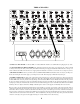
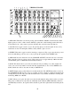
Removal of a module of 4 channels is accomplished by:
1) Unscrewing and sliding back the top perforated cover.
2) Pulling up and off the 4 IDC ribbon connectors from the headers.
3) Removing the 8 plastic nuts from the 1/4" jacks and the 8 black 4-40 screws from the combi jacks
4) Removing the 4 hex head 4-40 screws that hold the black engraved front panel.
5) Pull the module forward, and to the right to clear the XLR locks.
A single channel can be removed from the module by:
1) Disconnecting the wire or ribbon between the channel and the switch board.
2) Disconnecting the Buss Wire (48V) connecting the 4 channels.
3) Removing the 3 knobs, and nuts under that mount the pots and/or switch.
Each channel uses a pair of 30 ohm 1/2 watt resistors on the +/- 24 volt supplies for fusing and
isolation. They are next to the 2200uF filter caps, and are intended to smoke and fry if a serious short
exists in the channel and prevent much bigger problems.