
Owner`s manual
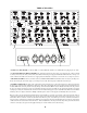
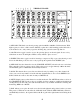
9) PHANTOM POWER. This switch is for the 48 volts needed for most solid state condensor mics.
It is not generally needed for tube mics, dynamic mics, ribbon mics and in some cases may be
harmful to some old vintage ribbon mics. Each switch is for a bank of 4 channels (1-4, 5-8, 9-12, 13-
16) and is a LOCKING TOGGLE which needs to be pulled to switch. This is a safety feature to
prevent huge pops from hurting speakers and sensitive ears. Mic signals are usually 1/100th of a
volt and phantom is 48 volts so a sudden change from switching phantom on or off can make a
horrendous thump. This can also happen if one plugs in a mic or mic cable or patch when phantom is
on. Try to get in the habit of turning down the channel and/or muting the Mix and Monitor to prevent
surprises and blown speakers. Also keep in mind, that slightly flaky mic cables or patch points may
seem much worse with phantom on. Phantom power may still be on even if the front panel power
switch is off because it is also used to remote control the main supply relays.
10) MIC CHANNEL INPUTS. These are COMBI jacks that allow either XLR or TRS plugs to be
used. With XLRs the input impedance is 2400 ohms which is suitable for mics but may be low for
some line level gear, especially semi-pro and consumer gear. The symptom would usually be
premature clipping. If one uses a 1/4" TRS plugs, then the input impedance switches to 82K ohms
which is an easy load for almost all gear including guitars and basses but probably too high for many
mics. In other words use XLR plugs with mics and TRS with instruments and either with pro line
level sources and it automatically works. With semi pro -10 dBv gear and synths, you will usually
get best performance with TRS plugs and turning the MIC GAIN up 1 notch to "15 dB" of gain.
PIN 1 = SLEEVE = GROUND = SHIELD
PIN 2 = TIP = HOT = Positive
PIN 3 = RING = LOW = Negative
These inputs allow inputs as hot as +30 dBu balanced or +24 dBu unbalanced before clipping when
the MIC GAIN is set for "0 dB", which is about 6 dB better than most pro gear can send, so clipping
the mic inputs with line signals should be unusual. The LINE INPUT channels use this same 0 dB
configuration. The MIC INPUTS also allow for 60 dB of maximum gain with the MIC GAIN turned
up sufficient for most miking situations with another 10 dB with the MIX levels cranked.
11) INSERT JACKS. These TRS jacks allow the amplified mic signals to be sent and returned from
a compressor, EQ, gate, etc. A front panel switch (INS) is used to turn on a relay to use the return or
to bypass the rack processing and extra components in the signal path. This insert is post mic pre, but
before the MIX gain, MUTE and PAN.
T= TIP = SEND, R= RING = RETURN, S = SLEEVE = Shield = Chassis Ground.
All signals are unbalanced and follow a standard wiring format used in many other mixers. There is
no point in providing and INSERT for the unity gain LINE INPUTS because we can patch an EQ or
other device between the source and mixer and retain balancing and headroom and avoid unneeded
extra components in the path but because Mic Preamps provide needed gain there is a definite need
for INSERTS there.
12) CHANNEL OUTPUTS. Balanced outputs used to feed individual tracks on a multitrack recorder
or A to D converter. These outputs are after the MIX GAIN controls but are not muted by the MUTE
button. So by muting, you can eliminate these channels from the mix buss but still send to a
recorder. This way, you can use the Mic Pre, Phase Switch, Insert and Mix Gain (for fine level
control) on its way to a multi-track. These outputs are capable of +30 dBm drive levels once again
enough to pin the meters of most anything.
T= TIP = HOT = +, R = RING = Low = -, S = SLEEVE = Shield = Chassis Ground.
6