
Owner`s manual
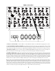
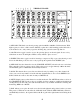
13) TAPE PLAYBACK INPUTS. Used for returning a 2 track tape machine or DAT back to the
mixer for monitoring, checking or just listening. Once one records a mix, it is always a good idea to
check playback. The 5 position monitor select switch on the front hast to be in the "TAPE" position
to hear the playback. These are balanced inputs, TIP hot.
14) EXT INPUTS. Used for chaining mixers for 32 channels if you have 2 mixers and the 1/4" MIX
outputs are fed from the other mixer into these jacks. On MIC VERSION mixers there is a gain
control on the front panel (EXT) and on LINE VERSION it is a unity gain input direct into the mix.
These inputs can be used as an effects return if not required for chaining mixers. These are balanced
jacks, TIP hot, RING neg.
15) AUX OUTPUT. Only on the LINE and 8+8 VERSIONS. This is the effect send or a mono
headphone send. Channels can feed this jack if their AUX control is turned up and the AUX knob in
the master section is also up. This is an unbalanced output on a balanced TRS jack and can be used
to feed balanced or unbalanced inputs.
16) SOLO LINK. If one has 2 mixers, they can simply connect a wire between these terminals to
link the SOLO system. This allows you to solo one channel and the other 31 channels mute. If the
16x2 is used as a "sidecar" for a large console, it might also be used to link to the solo system of the
larger desk. 12 volts = no solo, 0 volts = solo. This is a mini banana post and not the larger size used
on test gear.
17) GROUND POSTS. Generally, there should be a wire connecting these two posts. One is
CHASSIS GROUND which is also the third pin of the AC plug. The other post is AUDIO
GROUND which is the zero volt common of all the audio signals. Having these grounds accessible
is useful for solving hum problems and for installations with custom ground schemes. For reference,
all 1/4" TRS sleeves or shield points are taken to chassis ground, and all rings are taken to audio
ground via a 30 ohm resistor. The internal star ground reference is on the left tube board at the
summing transformers / power connector.
18) LINE INPUTS. These are COMBI jacks that allow either XLR or TRS plugs to be used. Unlike
the MIC INPUTS the input impedance is always 82K ohms which is an easy load for almost all gear
including guitars and basses. With semi pro -10 dBv gear and synths, if more gain is needed, a
resistor can be added on any channel to increase gain as required. See page XX for details.
PIN 1 = SLEEVE = GROUND = SHIELD
PIN 2 = TIP = HOT = Positive
PIN 3 = RING = LOW = Negative
These inputs allow inputs as hot as +30 dBu balanced or +24 dBu unbalanced before clipping which
is about 6 dB better than most pro gear can send.
19) CHANNEL OUTPUTS. Balanced outputs used to feed individual tracks on a multitrack recorder
or A to D converter. These outputs are after the MIX GAIN controls but are not muted by the MUTE
button. So by muting, you can eliminate these channels from the mix buss but still send to a recorder
with these jacks. This way, you can use the Mic Pre, Phase Switch, Insert and Mix Gain (for fine
level control) on its way to a multi-track. These outputs are capable of +30 dBm drive levels once
again enough to pin the meters of most anything.
T= TIP = HOT = +, R = RING = Low = -, S = SLEEVE = Shield = Chassis Ground.
7