
Instruction Manual
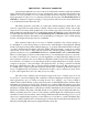


REAR PANEL
B
A
L
A
N
C
E
D
CIRCUIT
GROUND
CHASSIS
A B D E F G
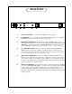
A IEC MAINS SOCKET - Accepts standard 50/60 Hz AC mains voltage.
B FUSE HOLDER - To remove the fuse, push and turn the fuse holder cap. Use a 1 Amp
SLO-BLO fuse. Always replace fuse with same value and type.
D GROUNDING TERMINALS - These binding posts allow installation into a variety of
different grounding schemes used by studios. Normally theCHASSIS GROUND and AUDIO
GROUND are connected with a "strap". CHASSIS GROUND is also third pin AC ground.
AUDIO GROUND could alternatively be connected with a wire to a star ground point
E 1/4" MONITOR OUTPUT - The 1/4" output is controlled by with the MONITOR
OUTPUT switch. It can be either parallel to the XLR output signal or derived from the
sidechain filters providing a way to tune the filters to the offensive frequency. It is meant to
feed a console channel not heard by the artist nor fed to tape.
F XLR UNBALANCED OUTPUT - This is an unbalanced output which will drive any
impedance down to 600 ohms, but an impedance of 1000 ohms or greater is preferred. Pin
out is as follows: PIN1 - ground, PIN3- ground (-), PIN2 - hot (+). This output is meant to
feed the recording machine safely. The maximum output level is greater than +32 dBv which
will provide ample headroom in all situations.
G XLR BALANCED INPUT - This input is transformer coupled floating balanced with PIN 1
connected to AUDIO GROUND, PIN 2 (+) connected as the positive going phase and PIN 3
(-) as the negative going phase. PIN 3 should be wired to the shield only if the source is
unbalanced. Connection to PIN 1 is optional depending on the grounding scheme of the
studio. The input impedance is greater than 20 Kilo-ohms. The unit will perform best with a
nominal +4 signal.
MONITOR MAIN OP