MANLEY LABORATORIES, INC. THE WAVE OWNER'S MANUAL TUBES RULE brought to you by the clever folks at: MANLEY LABORATORIES, INC. 13880 MAGNOLIA AVE. CHINO, CA. 91710 USA TEL: (909) 627-4256 FAX: (909) 628-2482 email: emanley@manleylabs.com website: www.manleylabs.
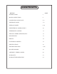
CONTENTS SECTION PAGE INTRODUCTION 3 MAINS CONNECTIONS 4 CONNECTING YOUR WAVE 5, 6 THE FRONT PANEL 7, 8 THE BACK PANEL 9, 10 THE EXTERNAL POWER SUPPLY 10 THE REMOTE CONTROL 11 THE GUTS, TRIMS, SWITCHES, ETC 12 DIP SWITCHES 13 ERRATA 14 FEATURES & CREDITS 15 SPECIFICATIONS 16 TROUBLE SHOOTING 17,18 BLOCK DIAGRAM 19 APPENDIX - WIRING CABLES 20 WARRANTY 21 WARRANTY REGISTRATION 22
INTRODUCTION THANK YOU for choosing the WAVE by MANLEY. You have possibly chosen this product because you auditioned it in a store or heard it at a HiFi show and were impressed with the sound. It may have been the right combination of price, power, features, and styling for you. It may have been because you know the Manley Labs reputation for quality, reliability and integrity. If any or all of these were the reasons, you made a good choice and for that, we thank you for all eternity.
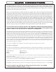
MAINS CONNECTIONS Your WAVE has been factory set to the correct mains voltage for your country. (Well, that is what we intended to do when we knew where it would be initially shipped.) The mains voltage that we built this WAVE to operate with is typed on the serial badge, located on the rear panel of the power supply chassis. Check that this agrees with what comes out of your wall.
CONNECTING YOUR WAVE Setting up the WAVE is rather easy but there is a lot of stuff to hook up... Please refer to page 9 for a diagram of the back of the WAVE. 1. You will be connecting power last and turning the system on after all other connections are made to prevent ugly noises as wires are connected and to prevent possible damage to your amps and speakers.
STILL CONNECTING YOUR WAVE 6. Turn ON the On/Off power switch (ON=1) and then push the STANDBY button to wake up the audio chassis. Let the WAVE warm-up for a few minutes. You should be seeing the blue LEDs light up and some more noticably bright than others. The MUTE button should have started out bright and probably went dim after 20 seconds. This is the warm-up delay which MUTEs the outputs until the unit is warmed up and ready to play tunes. You may push a few buttons at this point.
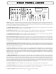
FRONT PANEL CONTROLS PH X 2 32K F S G 1 A 2 IF D 96K 3 T E T STAN 3 2 T MU RT E OU INS 4 T A S BY OU WAVE MANLEY S S A THE TT OO ND A C MM 48K SP 44K 88K O SE A E A D AE ABC BY D HANDCRAFTED WITH PRIDE IN CHINO, CALIFORNIA USA REMOTE CONTROLLED ALL-TUBE PREAMPLIFIER COMBO H I J K L The name "The WAVE" came from a comment from our former office manager, Mickey, (now departed, RIP, bless her) that the pattern of the blue LEDs on the faceplate looked like
MORE FRONT PANEL CONTROLS INSERT CONTINUED: NOTE 1) The insert send and return can be factory wired for either balanced or unbalanced loops. Balanced Inserts use XLR 3 pin connectors appropriate for professional reel to reel tape decks and pro EQs (like the Manley Massive Passive) or other balanced hifi gear. For a nominal charge we can also provide sensible tape monitor switching and input/output for 2 tape decks and EQ (but we expect very few will need this level of complexity).
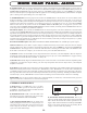
REAR PANEL JACKS LEFT The WAVE by MANLEY DAC / Preamp SERIAL NUMBER AN EVEANNA MANLEY PRODUCTION LINE STAGE DESIGNED BY C. HUTCHISON PCB'S & CHASSIS BY B. HERNANDEZ LOGIC DESIGNED BY J. GARSZVA RIGHT MANLEY LABORATORIES 13880 MAGNOLIA AVE., CHINO, CA 91710 PHONE (909) 627-4256 FAX (909) 628-2482 email: emanley@manleylabs.com DIGITAL I/0 OUTPUT 3 OUTPUT 2 BALANCED OUTPUT 1 UNSWITCHED INSERT RETURN INSERT SEND ANALOG 2 ANALOG 1 GROUND CIRCUIT CAUTION - RISK OF ELECTRIC SHOCK. DO NOT OPEN.
MORE REAR PANEL JACKS K) INSERT SEND: This is an analog output before the volume control designed to feed (SEND signal to) tape recorders or external processors, such as an equalizer, for instance. The WAVE is standardly configured with unbalanced RCA jacks for the INSERT SEND and RETURN, right on bottom, left on top. This SEND output is always on, even if INSERT is not selected. The active selected input of your eight inputs will also appear here as an analog signal.
AES A 1 Y A B OP ST ND M TOS A 3 ST A 4 SER THE WAVE BY T P DIF A 2 UTE IN If the remote's command LED fails to light when you push a button and the WAVE is ignoring the remote's commands, then the remote's batteries are probably dead. Get your phillips screwdriver out and remove the two screws on the remote back where it shows you to, slide the cover down, and you'll see 3 x AA 1.5 volt dead batteries to change.
INTERNAL ADJUSTMENTS INPUT SELECTION DIGITAL to ANALOG CONVERTER PASSIVE ANTIALIAS FILTERS OUTPUT SELECTION (& MUTE) INSERT 7044 7044 MASTER REGULATORS & WARM-UP DELAY LEFT GAIN TRIM SW-016 1 2 3 12AX7 MASTER 12AX7 1 2 1 2 3 HIFI HIFI LEFT JUMPER SETTING FOR AMPLIFIER GAIN 2,3=FACTORY SET 1,2=+18DBM(MASTER) NO JUMPER=+24BDM (PROFESSIONAL) RIGHT 3 4 SW-015 P-04,P-05 RIGHT GAIN TRIM P-06 The gain of the Wave's tube stages are set at the factory.
dip switches REAR VIEW BACK OF FRONT PANEL 1 2 3 P-06 BLACK *See notes below SW-015 P-04,P-05,P-06 "FACTORY DEFAULT" OUT 2,OUT 3 ALTERNATE 1 2 DIP SWITCHES DEFAULT MODE 3 P-04 RED P-05 BLUE 1 2 SW-016 3 "DRAWING NOT TO SCALE" 1 2 3 P-06 BLACK P-04,P-05,P-06 OUT 2, OUT 3 INDIVIDUALLY CONTROLLED SW-015 1 2 DIP SWITCHES DEFAULT MODE 3 P-04 RED P-05 BLUE 1 2 SW-016 3 Jumpers marked P-04, P-05, P-06 are used to change from the default mode where OUT 2 and OUT 3 alternate interlocke
ERRATA The WAVE's DAC uses Burr-Brown PCM1704 D-A converters operating at 96 KHz at all times. All inputs below 96 KHz are upsampled to 96 KHz before conversion. The upsampled output is clocked out via a Low Phase Noise/ Low Jitter precision crystal oscillator to eliminate any interface jitter or timing problems with the incoming datastream. Multiple power supplies are used, with additional regulation and filtering located near critical components.
FEATURES & CREDITS FEATURES: 24-Bit 96KHz Digital to Analog Converter Board DIGITAL PHASE / POLARITY SWITCH 4 x switchable digital inputs AES, SPDIF, ST Glass, Toslink 1 x SPDIF digital output pass-through 4 x Stereo ANALOG INPUTS: (standard: 2 x stereo unbalanced RCA, 2 x stereo balanced XLR) INSERT SEND and RETURN (Tape processor loop) Available balanced XLR or Unbalanced RCA Motorized ALPS quad-attenuator volume control Vacuum tube output stage (2 x 12AX7EH input tubes; 2 x 7044 JAN NOS USA output tubes)
MORE SPECIFICATIONS POWER: Outboard Power Supply is factory set for 100V, 120V or 220-240VAC operation for original destination country's mains voltage. Operating Mains Voltage: 120 to 240VAC operation changeable with power transformer re-wiring via internal switch and fuse value change. 100VAC operation changeover achieved via rewiring of power transformer PCB. Mains Voltage Frequency: 50~ 60Hz Mains Fuse Value: 1.5A SLO-BLO for 100 or 120V operation Mains Fuse Value: 0.
TROUBLESHOOTING Sing along with us: "Problems, problems, problems all day long....." NO POWER, NO INDICATORS, NADA - Does the power supply LED come on and is the Standby LED dim? If so, the unit is in standby mode. Push that STANDBY button to make him come alive. If all lights are dark, even the LED on the PSU, probably there's an issue with AC power. Is it plugged in? Check the fuse on the back panel.
MORE TROUBLESHOOTING HUM: Once again - several possibilities - several cures. Most likely it is a ground loop. Ideally each piece of gear should have one ground connection and only one. However, the short list of grounds include the AC mains plug, the chassis bolted to a rack with other gear, each input and each output. The two most common procedures are: try a 3 pin to 2 pin AC adapter (about a dollar at the hardware store).
BLOCK DIAGRAM INSERT A1 DIGITAL BOARD A2 A3 A4 ANALOG BOARD PHASE MUTE PASSIVE AES/EBU CONVERTER ANTI- VACUUM TUBE ALIAS LINE AMP FILTER S/PDIF DECODING SRC Dig.
WIRING YOUR OWN CABLES ? XLR MAL MALE VIEWED FROM THE BACK OR SOLDER SIDE 1/4" MONO PHONE JACK TIP XLR MAL MALE VIEWED FROM THE SIDE SLEEVE SHELL TIP SLEEVE 2 1 3 1/4" STEREO PHONE JACK TIP RING SLEEVE RING TIP XLR FEMAL FEMALE VIEWED FROM THE BACK OR SOLDER SIDE XLR MAL MALE VIEWED FROM THE SIDE SLEEVE SHELL 1 1/8" STEREO PHONE JACK R T 2 3 S BANTAM (PATCHBAY) JACK RING TIP R T S MANLEY GEAR - THIS PAGE CAME WITH GEAR WITH TRUE TRANSFORMER BALANCED XLR INPUTS AND OUTPUTS.
Manley Laboratories, Inc. WARRANTY STATEMENT effective 1/2006 All Manley Laboratories equipment is covered by a limited warranty against defects in materials and workmanship for a period of 90 days from date of purchase to the original purchaser only. A further optional limited 5 year transferrable warranty is available upon proper registration of ownership within 30 days of date of first purchase.
WARRANTY REGISTRATION We ask, grovel and beg that you please fill out this registration form and send the bottom half to: MANLEY LABORATORIES REGISTRATION DEPARTMENT 13880 MAGNOLIA AVE. CHINO, CA. 91710 USA Or you may FAX this form in to: +1 (909) 628-2482 or you may fill in the online warranty registration form found in the Tech Support section of our website www.manleylabs.