
Owner`s manual

INTERNAL ADJUSTMENTSINTERNAL ADJUSTMENTS
INTERNAL ADJUSTMENTSINTERNAL ADJUSTMENTS
INTERNAL ADJUSTMENTS
7044
7044
LEFT
RIGHT
DIGITAL to
ANALOG
CONVERTER
LEFT GAIN
TRIM
RIGHT GAIN
TRIM
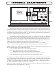
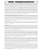
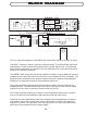
The gain of the Wave's tube stages are set at the factory. There are only 4 trimmers (2 per
channel) but because the input to the line amplifier is balanced and it is a minimum feedback design,
it requires a trimmer for each phase or leg. So both trimmers affect the gain and the "balance" of the
two trimmers affect common mode rejection. Yes, this could have been made more convenient, but
it would have compromised some sonic performance.
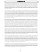
The method to adjust these requires an oscillator, AC voltmeter, CD test disk with 1K digital
full scale and a special banana to XLR M cable that allows the oscillator to send between: a) pin 1 &
pin 2, b) pin 1 & pin 3, c) pin 2 & pin 3 (normal balanced) and d) between pin1 & pin2+pin3 (for
CMRR). These tests are done with the Volume control turned up full, the appropriate input selected
(nothing else) and no amplifiers connected and the Wave well warmed up.
It is not difficult but be careful - high voltages are right around the tubes. Use an insulated
screwdriver, keep one hand in your pocket and don't touch the screwdriver to any other parts.
With the oscillator set to 1 kHz and 1 volt AC RMS and the AC voltmeter meter reading Output A of
the same channel and the special cable hooked up for:
test a) the output should read 1.3 volts. If not adjust trimmer 1
test b) the output should read 1.3 volts. If not adjust trimmer 2
Repeat this several times due to interaction between the trims.
test c) should now read 4.5 volts. If not, make sure you did a) and b) correctly.
test d) should read 0.0 volts and common mode cancellation should occur.
You may have to slightly & carefully tweak either trimmer 1 or 2 to provide the deepest cancellation
and you should either switch the meter to the most sensitive scale or adjust this while listening to the
output and trimming for the lowest possible signal. If you attempt to do this listening to the output,
be careful, slow and don't change any cables until you turn off the amps. A sudden change from a
tiny signal to full tilt 1K oscillator can easily blow a speaker.
Amps are off, back to using the AC voltmeter? Good, insert the test CD, select that digital input and
the 1K full scale track. You should read 2 volts now.
OUTPUT
SELECTION
(& MUTE)
INSERT
INPUT
SELECTION
1 2 3 4
P-04,P-05
SW-016
SW-015
P-06
PASSIVE
ANTI-
ALIAS
FILTERS
REGULATORS
& WARM-UP
DELAY
1
2
3
HIFI
MASTER
1
2
3
HIFI
MASTER
12AX7
12AX7
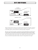
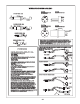
JUMPER SETTING FOR
AMPLIFIER GAIN
2,3=FACTORY SET
1,2=+18DBM(MASTER)
NO JUMPER=+24BDM
(PROFESSIONAL)
12