
Owner`s manual

A B C D E F G
H I J K L
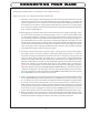
The name "The WAVE" came from a comment from our former office manager, Mickey, (now departed, RIP, bless her)
that the pattern of the blue LEDs on the faceplate looked like an ocean wave breaking. "It looks like a Wave!" She
exlaimed when she saw the first prototype that EveAnna Manley and Baltazar had made. The buttons glow dimly to
assist in darkened rooms, and only glow brightly when that function is selected and active.
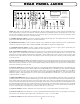
A) INFRARED SENSOR: This is the reciever for the infrared remote control. It doesn't light up, ever.
B) COMMAND: Indicator to show a valid command from the remote control or front panel. Push any button and watch
him blink in sync with the transmission codes. He's letting you know that he hears your command.
C) SAMPLING RATE INDICATORS: These light up to show the incoming digital signal's sample rate and will not
light until the digital input circuitry has locked onto valid data. There are three LEDs marked 32, 44.1, & 48 and these
will light up to indicate one of those frequencies in kilohertz. If an 88.2 or 96KHz sample rate signal is present, the x2
LED will come on (same as 32KHz LED) in addition to the appropriate 88 or 96KHz LED. Simple math in action.
D) PHASE: Reverses the polarity of the Digital Converter when pushed and lit. This can be a subtle effect however
because it is performed in the digital domain does not degrade fidelity. It has no effect on any analog inputs. Really.
Promise. Trust me.
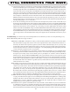
E) DIGITAL INPUT SELECT: Pushing one of these 4 buttons selects from either the AES/EBU, S/PDIF, Toslink, or
ST (glass fiber) Inputs to the Digital to Analog Converter and S/PDIF digital output. The last button pushed (of these
four) stays illuminated even if one of the four ANALOG INPUT SELECT buttons is pushed to indicate which digital
source is still feeding the digital output, presuming a valid digital signal clock is still present. This feature allows one
to use an external DAC which could return into any of the analog inputs, and allows for easy digital recording.
F) ANALOG INPUT SELECT: Pushing one of these four buttons selects that one to be the active analog input. In
conjunction with the DIGITAL INPUT SELECT, whichever the last of these eight buttons was pushed is the selected
input and that what is what you will hear.
G) VOLUME CONTROL: I guess we don't really have to explain what this does but we can tell you it is a custom-made
precision 4 gang conductive plastic motorized ALPS 50Kohm potentiometer. Two decks are used per channel because
the signal is balanced at this point before feeding the differential input of the tube line amplifier.
H) INSERT: If you know what a TAPE LOOP or PROCESSING LOOP is, then you know what this button does. It
allows an external device like a tape machine or equalizer to be used with the selected source and breaks or interrups
the normal signal flow right before the Volume Control. SEND "sends" the signal to your external destination. RETURN
"returns" the signal path back to the WAVE. "INSERT" is a word borrowed from professional audio as processors are
"inserted" into the recording path. If you not have anything plugged into the TAPE LOOP, then when the button is
pushed, the signal is going to nowhere and not coming back from anywhere, and the tunes are not continuing through
the WAVE. If this is annoying, just use a simple short pair of interconnects to patch the INSERT SENDs to the INSERT
RETURNs to defeat the INSERT button, in effect.
7
FRONT PANEL CONTROLSFRONT PANEL CONTROLS
FRONT PANEL CONTROLSFRONT PANEL CONTROLS
FRONT PANEL CONTROLS
T
O
S
S
S
T
A
N
D
B
Y
M
U
T
E
O
U
T
3
O
U
T
2
I
N
S
E
R
T
A
E
S
A
1
A
2
S
P
D
I
F
A
3
A
4
S
T
P
H
A
S
E
T
O
S
4
8
K
C
O
M
M
A
N
D
X
2
REMOTE CONTROLLED ALL-TUBE PREAMPLIFIER COMBO
THE
MANLEY
HANDCRAFTED WITH PRIDE IN CHINO, CALIFORNIA USA
BY
WAVE
9
6
K
8
8
K
3
2
K
4
4
K