
Owner`s manual
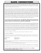
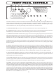
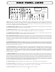

P O N M L K J I H G F E D C B A
NOTE: This panel shows the WAVE as it standardly ships. However, Manley Labs does custom configure individual units to
order with alternative connectors and different variations of balanced and unbalanced inputs and outputs, but we don't write
custom owner's manuals for them. This drawing may not accurately depict your exact jacks, if you had us do something custom
for you, but you should get the gist of it from this drawing.
A) AES/EBU DIGITAL INPUT: Connect the appropriate balanced digital input here. The digital interconnect should be a
proper digital AES XLR cable optimised for 110 ohm termination.
B) S/PDIF DIGITAL INPUT: As above, but the consumer version, unbalanced 75 ohm on an RCA jack. Very popular but this
interface is designed for shorter cables. Both the AES/EBU and S/PDIF are transformer coupled inputs.
C) TOSLINK DIGITAL INPUT: Another popular standard interconnect that uses a square plastic optical fiber jack.
Unfortunately it is best avoided for sonic reasons unless no other option exists.
D) ST-GLASS DIGITAL INPUT: Generally the best choice as it uses a premium glass fiber that provides the widest bandwidth,
fastest square waves, and best electrical isolation. Unfortunately, many players do not include this due to cost reasons. This
standard was created by AT&T and adopted for digital audio. These small bayonette style connectors require a quarter turn
clockwise to lock. The cable and connector can be fragile so please treat him gently when connecting or disconnecting cables
or moving the unit.
E) SELECTED DIGITAL OUTPUT: This S/PDIF output follows the last selected digital input (even if one of the analog Inputs
has been selected). This allows for digital to digital recording. The front panel LEDs indicate the last selected digital source.
Older Panasonic DAT machines may or may not be capable of dealing with this output, in our experience, but who else besides
us has those nowadays anyway? Oh well.
F) ANALOG 1 INPUT: The standard WAVE provides two stereo unbalanced RCA LINE LEVEL inputs (compatable with most
hi-fi and consumer equipment) and two balanced XLR stereo LINE LEVEL inputs (compatable with some premium audiophile
equipment and pro gear). These are not phono inputs (which require way more gain, different impedances, and the RIAA
equalization curves). You can plug line level outputs from a phono preamplifier, AM/FM receiver, tape deck, iPod line or
headphone outputs or VCR audio outputs, etc. into any of these analog line linputs (or ANALOG 2, 3 or 4). This Analog 1 input
is selected with the A 1 button.
G) GROUND TERMINALS: These ground posts are intended to help in some installations particularly where a special audio
grounding scheme is used. The top black mini-binding post is the audio circuit ground and the bottom green mini binding post
is the chassis ground. We ship these already connected together with a piece of buss wire running between them. Have a look.
Note: the AC mains "third pin" ground is tied to the power supply chassis which is consequently tied to the WAVE audio chassis.
For almost all applications these green and black ground posts should remain connected together and in most cases, you should
leave that connecting wire right where it is. If you are getting hums and buzzes, you can start experimenting with lifting the
circuit-to-chassis link and re-grounding these grounds to other parts of your system.
J) ANALOG 2 INPUT: Just like ANALOG 1 but corresponds to the A 2 input select button. No surprises here....
I) ANALOG 3 INPUT: Just like ANALOG 1 except typically built as balanced XLR connector corresponding to the A3 input
select button on the faceplate. Pinout will be Pin 1: Ground, Pin 2 (+), Pin 3 (-) for the XLR's.
J) ANALOG 4 INPUT: Just like ANALOG 3 but use the A4 button to select this guy.
9
REAR PANEL JACKSREAR PANEL JACKS
REAR PANEL JACKSREAR PANEL JACKS
REAR PANEL JACKS
DAC / Preamp
by MANLEY
The WAVE
ANALOG 4 ANALOG 3 ANALOG 2 ANALOG 1
AES / EBU
LOGIC DESIGNED BY J. GARSZVA
PCB'S & CHASSIS BY B. HERNANDEZ
LINE STAGE DESIGNED BY C. HUTCHISON
AN EVEANNA MANLEY PRODUCTION
email: emanley@manleylabs.com
PHONE (909) 627-4256 FAX (909) 628-2482
13880 MAGNOLIA AVE., CHINO, CA 91710
MANLEY LABORATORIES
PIN 3 = LOW = NEGATIVE PHASE
PIN 2 = HOT = POSITIVE PHASE
PIN 1 = SHIELD = GROUND
XLR INPUTS AND OUTPUTS
MOISTURE
THIS EQUIPMENT TO RAIN OR
ELECTRIC SHOCK DO NOT EXPOSE
TO REDUCE THE RISK OF
SERIAL NUMBER
PERSONNEL ONLY
REFER SERVICING TO QUALIFIED
SHOCK. DO NOT OPEN.
CAUTION - RISK OF ELECTRIC
DIGITAL I/0
POWER SUPPLY
GROUND
CHASSIS
CIRCUIT
OUTPUT
DIGITAL
SELECTED
ST TOSLINK S/PDIF
LEFT
RIGHT
SEND
INSERT
RETURN
INSERT
BALANCED UNSWITCHED
OUTPUT 2OUTPUT 3 OUTPUT 1